Method for the correction of spherical aberration in microscopic applications

a technology for microscopic applications and aberrations, applied in closed circuit television systems, instruments, television systems, etc., can solve the problems of requiring more time, requiring manual adjustment, and local variation of spherical aberrations, so as to minimize the number of recordings needed for the correction algorithm, the effect of maximizing the time resolution

Active Publication Date: 2015-09-10
CARL ZEISS MICROSCOPY GMBH
View PDF10 Cites 5 Cited by
  • Summary
  • Abstract
  • Description
  • Claims
  • Application Information

AI Technical Summary

Benefits of technology

[0054]In this way it is possible to minimize the time requirements and phototoxicity and maximize the time resolution.
[0055]If the accuracy of the interpolated correction values is not sufficient for the application, the values from the interpolated correction matrix may advantageously be used as starting values for the correction passes. The starting values are then very close to the optimal values. The number of recordings needed for the correction algorithm may be minimized in this way. This reduces the required time, increases the time resolution, and minimizes the phototoxicity of the overall correction procedure. By processing the positions to be handled in a suitable sequence, the network of grid points which are already known may be refined step by step, so that the interpolation becomes increasingly more accurate.
[0056]The structure of living preparations, for example Drosophila embryos or cells on a cover glass, changes over time. In the process, the spherical aberration may also locally change. In order to optimize the speed of the correction and to minimize phototoxicity to the greatest extent possible, the correction values determined in the respective preceding pass may be used as starting values. This allows optimal image quality, even for specimens which vary over time.
[0057]In addition, in the event of spherical aberration in the z-stacks which varies in the preparation in the axial direction, it is advantageous to retrieve the correction matrix at an identical lateral position and use it for the image recording, wherein, depending on the experiment, test recordings are made at different times in order to determine changes in the spherical aberration and in the detection over time.
[0058]If no change is identified, the existing correction matrix for the z-stack may be used. If the spherical aberration changes over time, a new correction pass may be started. This likewise allows continuous tracking of the correction, and optimal image quality, even for specimens which vary over time in three dimensions.

Problems solved by technology

The locally varying optical path length which results leads to locally varying spherical aberration.
However, as soon as z-stack, multiposition, panoramic, and / or time series experiments are carried out in multiple fluorescence channels, for example, manual adjustment is no longer practicable.
The numerous recordings not only require more time, but also mean a high phototoxicity level in the specimens to be investigated.
In fluorescence imaging, this means increased bleaching of the specimen.
In living cell applications, this results in undesired stress on the specimen.
In experiments in which a large number of recordings is carried out, this results in a significant increase in examination time, and a limitation of the achievable time resolution.
Thus, for example, scanning a 96-well plate with only one image per well would take an additional 8 minutes per pass, resulting in a significant limitation of the achievable time resolution.
The time expenditure for correcting the spherical aberration may exceed the duration of the actual image recording.
Depending on the correction procedure, it is also possible that no optimum for the correction is found.
Here as well, numerous time-consuming image recordings are necessary for measuring the spherical aberration and determining the correction value.
In particular in combination with multiposition and time series experiments, this results in an unacceptable time resolution and phototoxic stress on the specimen.
An optimal correction would then not be possible.

Method used


Image

  • Method for the correction of spherical aberration in microscopic applications
  • Method for the correction of spherical aberration in microscopic applications

Examples


Embodiment Construction

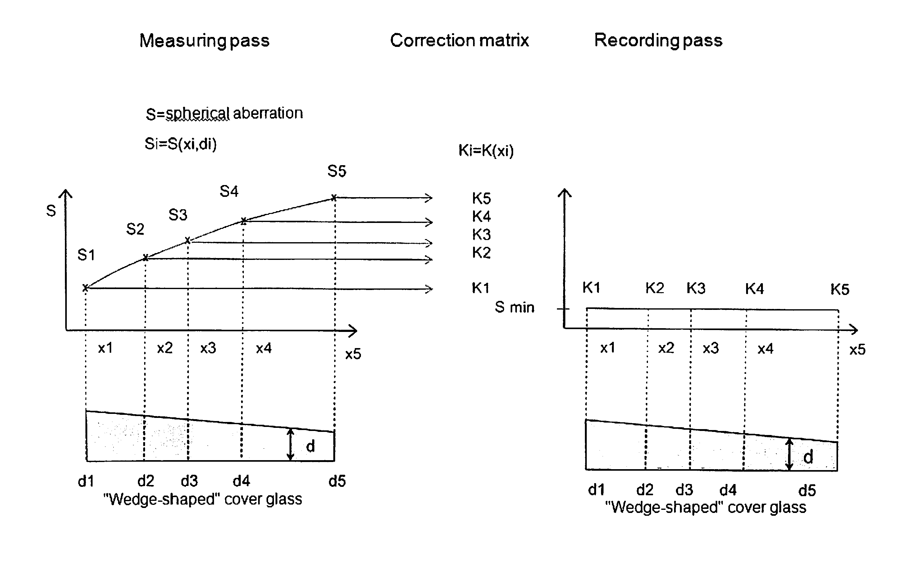
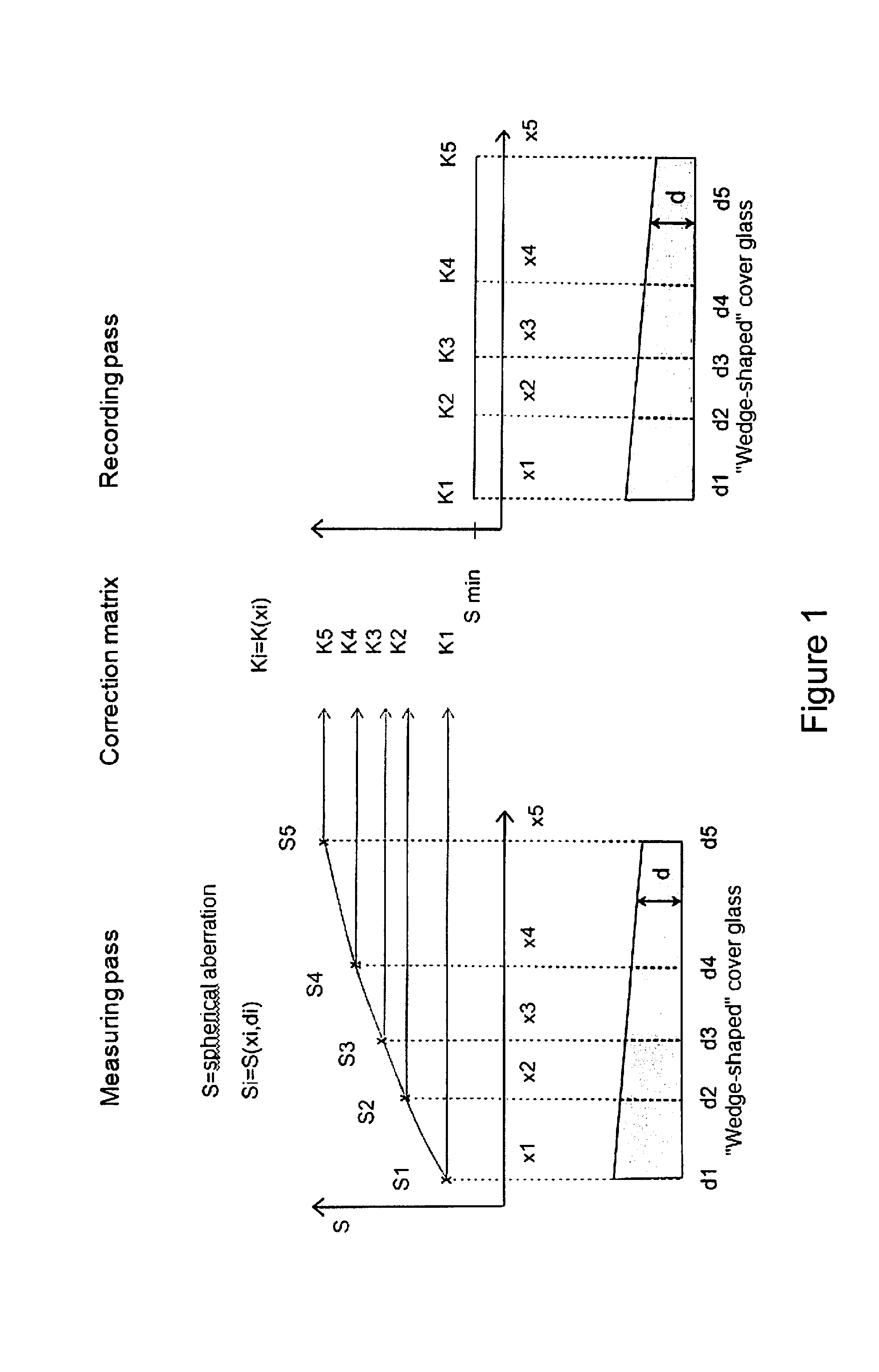
[0063]Spherical aberration is a function of a plurality of parameters. In a typical experiment, the spherical aberration is determined by the position x, y, and z, the wavelength λ, the cover glass thickness d, the index of refraction n1 of the cover glass, the index of refraction n2 of a specimen, and the penetration depth 1 into the specimen, resulting in the following dependencies:

Sijk=S(xi,yi,zk,λij,lik,di,n1i,n2i, . . . ),

where i is the index for the particular measuring / recording position, j is the index for the particular wavelength, and k is the index for the axial position, for example within a z-stack. The exact determination and correction of the spherical aberration and the setting of the correction matrix are dependent on the correction procedure used.

[0064]In a first example, the correction is described using a correcting objective by turning a correction ring. In this case, the position of the correction ring corresponds to a spherical aberration to be corrected. Thus...


PUM


Abstract

A procedure for the correction of spherical aberration in microscopic applications, wherein various recordings of a specimen to be observed are taken and evaluated for the purpose of changing the setting values of the optical system. The correction values are stored in a correction matrix as a function of the recording position, the recording time, the wavelength, and the temperature, wherein the determination and storage of the correction values are carried out in each recording position in the x, y, and z coordinates, and/or the correction values are determined after a selection of grid points by interpolation, so that the correction values of the interpolated correction matrix are the starting values for the subsequent exact determination by measurement.

Description

RELATED APPLICATION[0001]The present application claims priority to German Application No. 10 2014 103 145.4 filed Mar. 4, 2014, said priority application being incorporated herein in its entirety by reference.FIELD OF THE INVENTION[0002]The invention relates to a procedure for correction of spherical aberration in microscopic applications, and in particular, wherein various recordings of a specimen to be observed are taken and evaluated for the purpose of changing setting values of an optical system.BACKGROUND OF THE INVENTION[0003]Approaches are known in light microscopy, in particular in high-resolution microscope systems for biomedical applications, in which spherical aberration is corrected in an automated manner.[0004]The reason for the occurrence of spherical aberration is that vessel bottoms have locally fluctuating thicknesses and / or indices of refraction. In addition, locally fluctuating thicknesses and indices of refraction occur due to the structure and composition of th...

Claims


Application Information

Patent Timeline
Patent Type & Authority Applications(United States)
IPC IPC(8): G02B21/36H04N5/238
CPCG02B21/367H04N5/238G02B21/361G02B27/0025H04N23/75
Inventor KUES, THORSTENSTEINMEYER, RALF
Owner CARL ZEISS MICROSCOPY GMBH
Why Eureka
Try Eureka