
Apparatus and method for three dimensional image reconstruction

a three-dimensional image and image reconstruction technology, applied in image enhancement, image analysis, instruments, etc., can solve the problems of reducing the image acquisition efficiency of the specimen, unable to distinguish between structures, and unable to provide high resolution and high depth of field. , to achieve the effect of reducing the effect of photobleaching and phototoxicity, and reducing the effect of motion

Inactive Publication Date: 2007-03-27
CREATV MICROTECH
View PDF2 Cites 34 Cited by
  • Summary
  • Abstract
  • Description
  • Claims
  • Application Information

AI Technical Summary

Benefits of technology

[0009]An object of the present invention provides a hybrid optical system / computational approach that can extract comparable three-dimensional (3D) information from a single focal plane. This approach may improve image acquisition efficiency, eliminate effects caused by motion and minimize problems such as photobleaching and phototoxicity.

Problems solved by technology

The three-dimensional (3D) nature of thick specimen presents a difficult challenge for imaging with two-dimensional (2D) detectors.
Traditional microscopy methods can not simultaneously provide high resolution and high depth of field.
Nor can they distinguish between structures that are in front and in back of the focal plane.
This is an inefficient process that leads to limitations in certain circumstances.
The most serious problems are phototoxicity when imaging live tissue, photobleaching of weakly fluorescent specimens, and slow image acquisition of thick specimen.
Furthermore, the costs and maintenance needs of confocal and two photon microscopes render them less accessible to many users.
The disadvantages of this approach are the long reconstruction time, uncertain image convergence and the prerequisite of a z-stack of images, which requires long image acquisition time and causes photobleaching and phototoxicity.

Method used


Image

  • Apparatus and method for three dimensional image reconstruction
  • Apparatus and method for three dimensional image reconstruction
  • Apparatus and method for three dimensional image reconstruction

Examples


implementation examples

I. Example of One Implementation

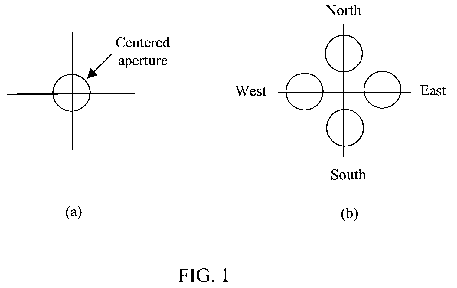
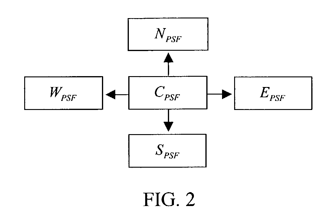
[0077]A more detailed description of an algorithm of an embodiment of the present invention is now provided. The algorithm of this embodiment is composed of four main parts: obtaining PSF; optical sectioning; deconvolution; and 3D image displays. The following example uses four directional images. The off-axis apertures are identical in shape to the centered aperture. They are located at equal distance from the axis and space 90 degrees apart in angular direction as shown in FIG. 1.

A. Obtaining Point Spread Function

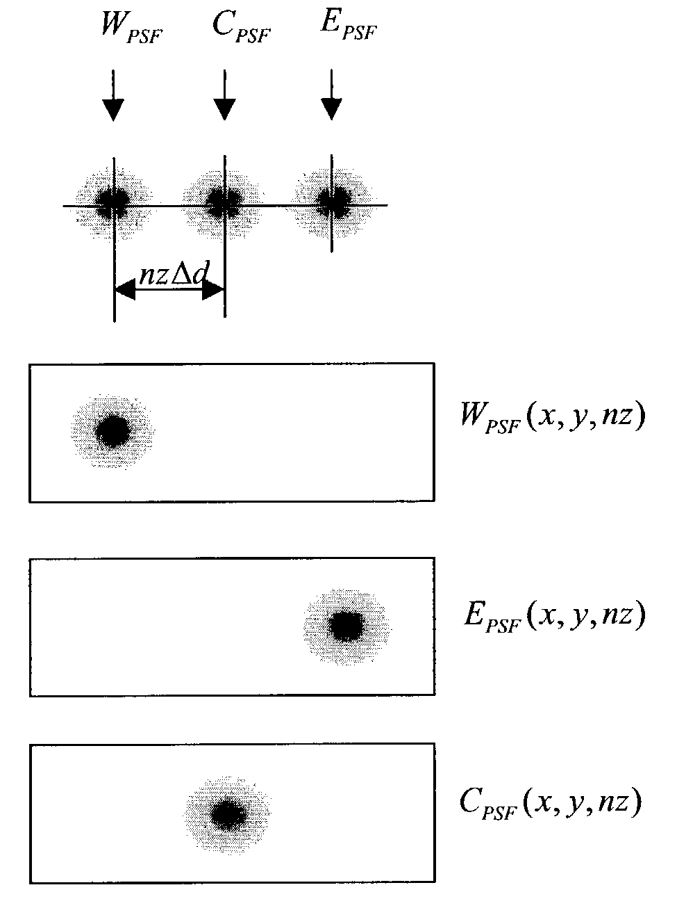
[0078]PSF can be obtained using sub-resolution micro-beads. The micro-bead images for the centered and directional apertures are CBEAD, SBEAD, NBEAD, WBEAD, and EBEAD, respectively. For ease of visualization and manipulation, the centered and direction micro-bead images can each given a different color and assembled together into one color image to evaluate the shift of the peak of the PSF. As an example of one micro-bead, FIG. 3 shows the ...


PUM


Abstract

An instrument to acquire and methods to obtain three-dimensional (3D) images from a series of two-dimensional (2D) images which are obtained without moving the relative positions of the target, the detector, or the focusing lens is disclosed. The 2D images consist of one centered image obtained with the aperture at the center of optical system, and at least two directional images obtained with apertures at off-axis locations. The images can be obtained simultaneously or sequentially. The blurred 2D images are sectioned by computational method using point spread function of the optical system resulting in a set of decoupled 2D layers of the 3D object. The layered images are then sharpened by deconvolution using point spread function. The 3D reconstructed image is displayed. This technique provides fast data acquisition and fast image reconstruction and eliminates problems associated with motion, phototoxicity and photobleaching.

Description

CROSS REFERENCE TO RELATED APPLICATIONS[0001]This application is a continuation-in-part application of U.S. patent application Ser. No. 10 / 427,999, entitled “Three Dimensional Image Reconstruction Algorithm”, which was filed on May 2, 2003, now abandoned by Shuhong Li et al.GOVERNMENT INTEREST[0002]The invention was made with Government support under Grant No. R43 MH60528, awarded by the National Institutes of Health. The Government may have certain rights in the invention.[0003]Related subject matter is disclosed in co-pending U.S. provisional patent application Ser. No. 60 / 377,225, filed May 3, 2002, the entire contents of which are incorporated by reference.FIELD OF THE INVENTION[0004]This invention relates to three-dimensional (3D) image reconstruction of thick objects. It is useful in microscopy, photography and diagnostic medical imaging, but is not limited to these applications. An aspect of this invention provides an instrument to acquire images and a method to reconstruct a...

Claims


Application Information

Patent Timeline
IPC IPC(8): G06K9/36G06T7/00
CPCG06T7/0065G06T2207/30024G06T2207/10056G06T7/55
Inventor LI, SHUHONGTANG, CHA-MINTANG, CHA-MEI
Owner CREATV MICROTECH
Learn More