
Dynamic radio frequency mapping

a radio frequency and dynamic mapping technology, applied in the field of dynamic rf mapping, can solve the problems of minimal (and sometimes no) consideration of sampling requirements, relative slow and expensive, and insufficient explanation as to the origin of any estimation error

Inactive Publication Date: 2015-09-10
THE ARIZONA BOARD OF REGENTS ON BEHALF OF THE UNIV OF ARIZONA
View PDF6 Cites 9 Cited by
  • Summary
  • Abstract
  • Description
  • Claims
  • Application Information

AI Technical Summary

Benefits of technology

This patent describes a system that can map out different RF signals in real-time. The system can quickly identify and locate RF signals in a variety of situations, making it useful in various applications.

Problems solved by technology

Due to the extensiveness of these modeling and data collection methodologies, they are relatively slow and expensive.
There is minimal (and sometimes no) consideration on the sampling requirements and corresponding error in these techniques.
As such, there is not an adequate explanation as to the origin of any estimation error.
But because an RF map cannot be separated from its samples to introduce an anti-aliasing filter, filtering the entire RF map is not necessarily an option.
A further challenge to existing mapping techniques is that the Nyquist sampling rate in most cases (e.g., small-scale fading for signals with a center frequency in the order of GHz) will result in an arbitrarily large number of required sampling points.
Such a number of points is practically impossible to implement.
Because sensors cannot be deployed in the order of centimeters, estimation errors due to aliasing are unavoidable.

Method used


Image

  • Dynamic radio frequency mapping
  • Dynamic radio frequency mapping
  • Dynamic radio frequency mapping

Examples


Embodiment Construction

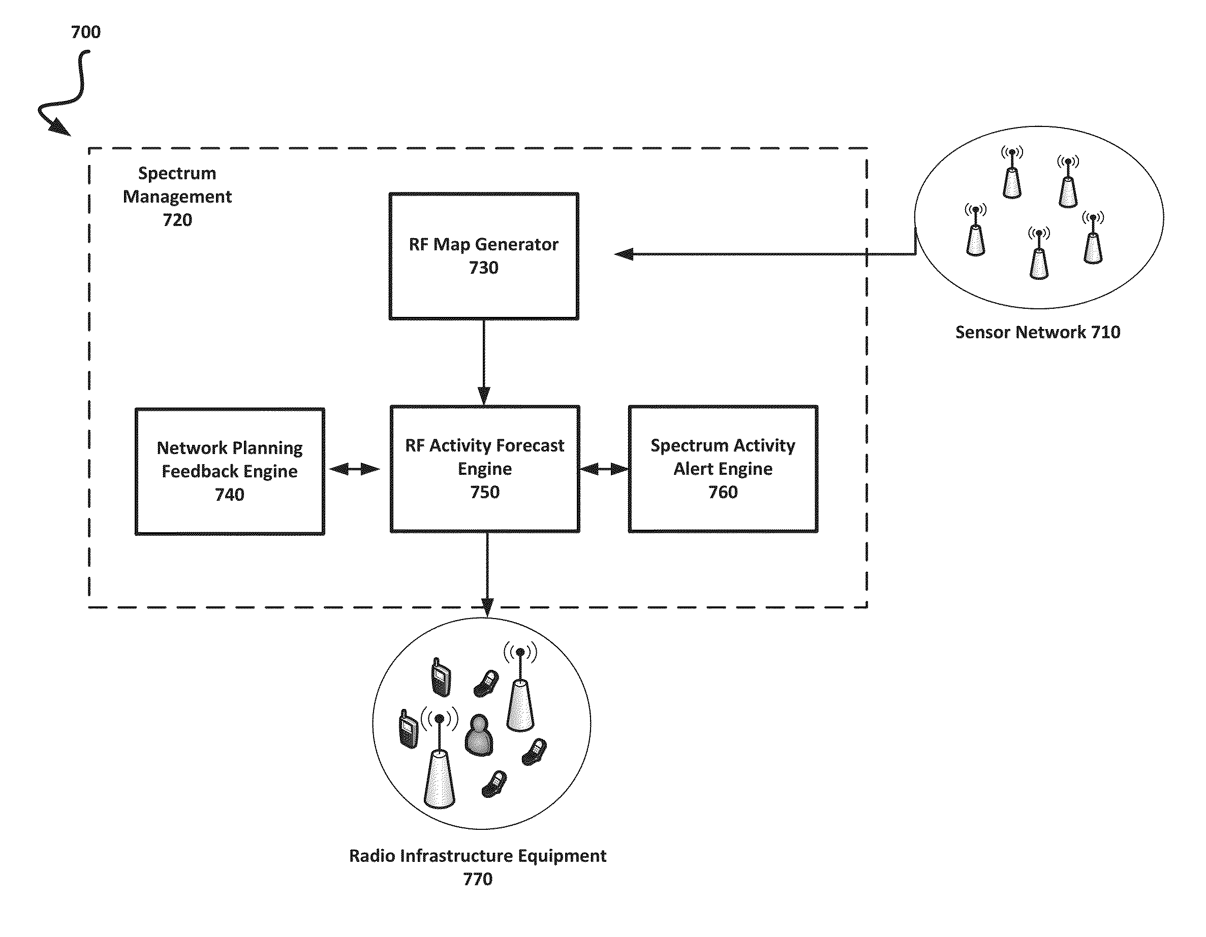
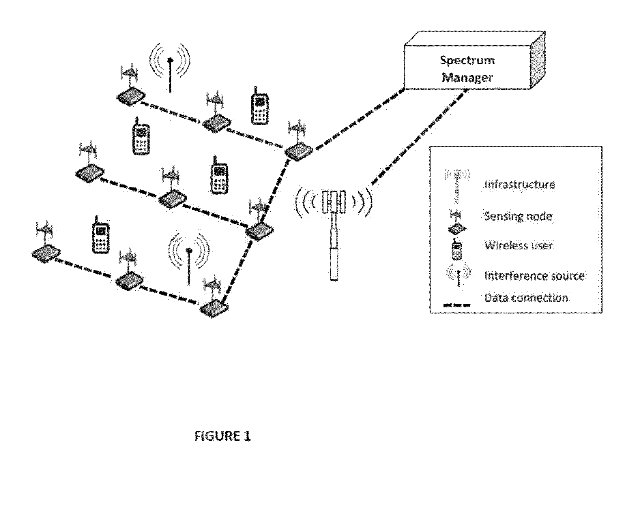
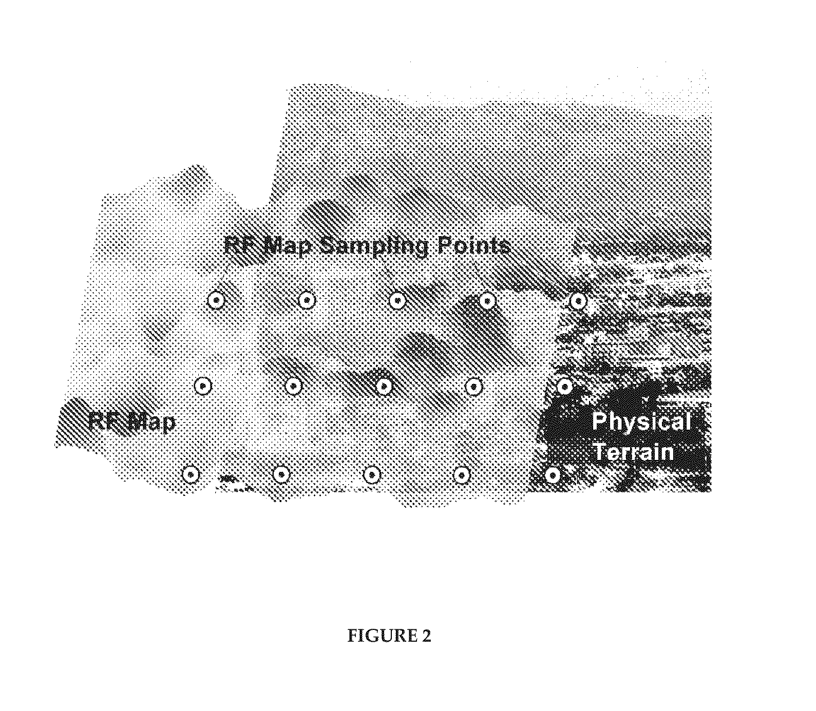
[0019]Embodiments of the present invention provide for a dynamic radio frequency mapping system that facilitates spectrum management and brokerage over a geographic area. The system is based on a network of spectrum sensing nodes that are distributed over a geographic area to be mapped. From information provided by the sensing nodes (sampling points), an RF activity map is generated.

[0020]The generated RF map contains information about the RF power levels in frequencies of interest over the geographical area. The RF map may also contain other information about the transmitters, including type of signal, specific transmitter identification, and operator. From observations of a current map, historical data from prior maps, and information concerning other major activity in a geographic area (e.g., earthquakes, sporting events, and trade fairs), the future RF activity for that area can be forecast. Using RF activity forecasts and indicia of current RF activity, future spectrum needs ca...


PUM


Abstract

An intelligent cognitive radio system is disclosed that acquires information about its environment to make operational decisions. Dynamic radio frequency mapping provides estimates of RF power levels over an area where spectrum activity or changes in the environment may be transient. These power levels can be used for a variety of applications such as interference management, spectrum policing, and facilitating spectrum auctions. The RF mapping can be accomplished by a network of sensors that are distributed in a geographical area and used to spatially sample signal levels. The present invention can quantify the effect of aliasing on the estimation of an RF map as a function of the sampling density and the number of antennas used at the sensing node.

Description

CROSS-REFERENCE TO RELATED APPLICATIONS[0001]The present application claims the priority benefit of U.S. provisional application No. 61 / 950,805 filed Mar. 10, 2014 and entitled “Dynamic Radio Frequency Mapping System,” the disclosure of which is incorporated herein by reference.BACKGROUND OF THE INVENTION[0002]1. Field of the Invention[0003]The present invention generally relates to radio frequency (RF) power levels in a geographical area. More specifically, the present invention relates to dynamic RF mapping to estimate RF signal power in areas where the physical environment or spectral activity rapidly evolves.[0004]2. Description of the Related Art[0005]The estimation of RF power levels in a geographical area is necessary for the planning and management of wireless networks. Current methods to map RF power levels involve extensive modeling and data collection throughout an area to be mapped. Due to the extensiveness of these modeling and data collection methodologies, they are re...

Claims


Application Information

Patent Timeline
IPC IPC(8): H04W72/04H04W72/08
CPCH04W72/085H04W72/0453H04W72/00H04W72/04H04W84/18H04W16/14H04B17/3913
Inventor BOSE, TAMALVOLOS, HARISVANHOY, GARRETTHIRZALLAH, MOHAMMEDBASTIDAS, CARLOS
Owner THE ARIZONA BOARD OF REGENTS ON BEHALF OF THE UNIV OF ARIZONA
Learn More