Self-Cleaning Rake

Inactive Publication Date: 2015-09-17
RIGGS DONALD +1
View PDF13 Cites 5 Cited by
  • Summary
  • Abstract
  • Description
  • Claims
  • Application Information

AI Technical Summary

Benefits of technology

[0023]Another object of the present invention is to provide a self-cleaning rake that may be rea

Problems solved by technology

This arrangement is inconvenient as the user must take his or her hand off of the rake handle and instead grab the handle for the push bar in order to remove debris from the rake.
Thus, Stapley discloses a device with two sets of tines that move relative to one another to remove debris, and fails to disclose a set of tines having a cleaning bar thereon that can be moved along the length of the tines in order to dislodge debris thereon.
While Nace discloses the design for a self-cleaning

Method used


Image

  • Self-Cleaning Rake
  • Self-Cleaning Rake
  • Self-Cleaning Rake

Examples


Embodiment Construction

[0031]Reference is made herein to the attached drawings. Like reference numerals are used throughout the drawings to depict like or similar elements of the self-cleaning rake of the present invention. For the purposes of presenting a brief and clear description of the present invention, the preferred embodiment will be discussed as used for cleaning debris from the tines of a rake. The figures are intended for representative purposes only and should not be considered to be limiting in any respect.

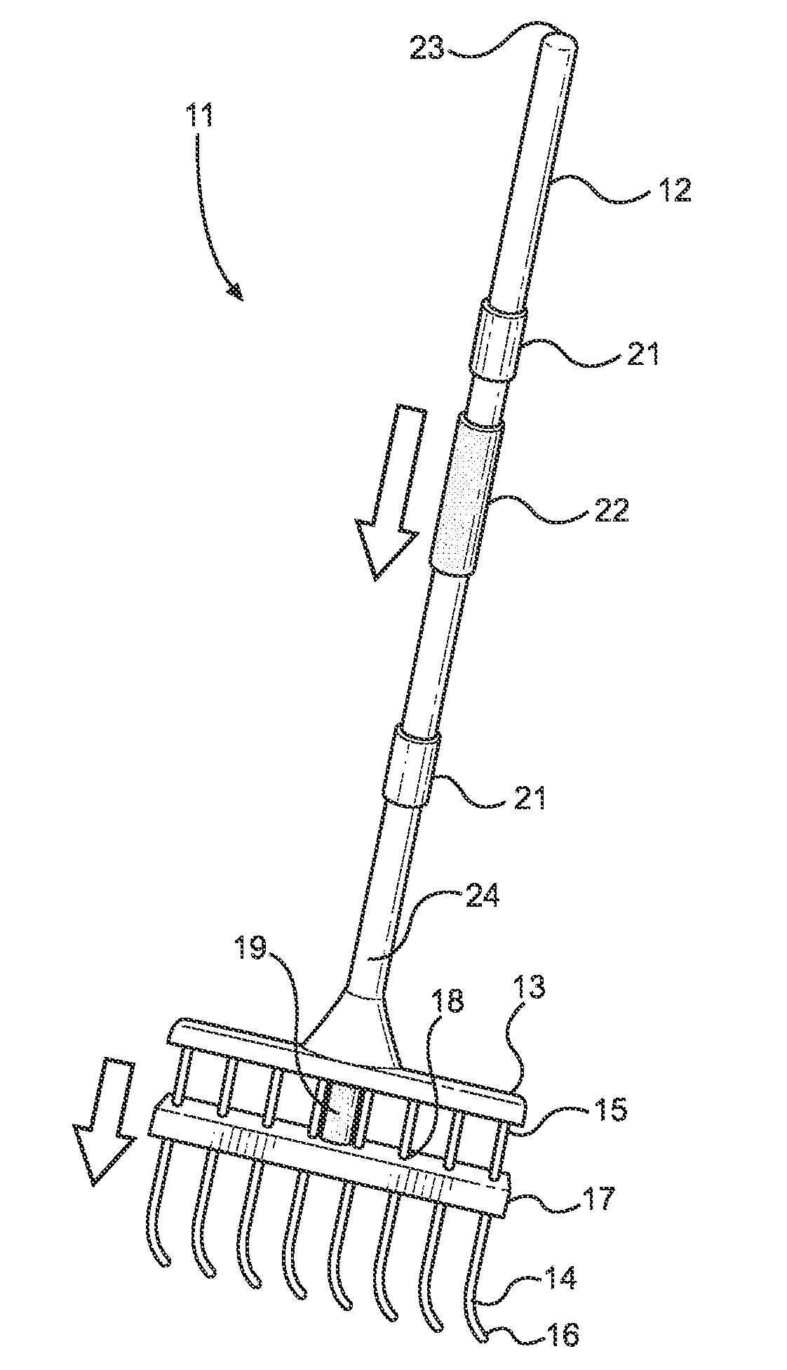
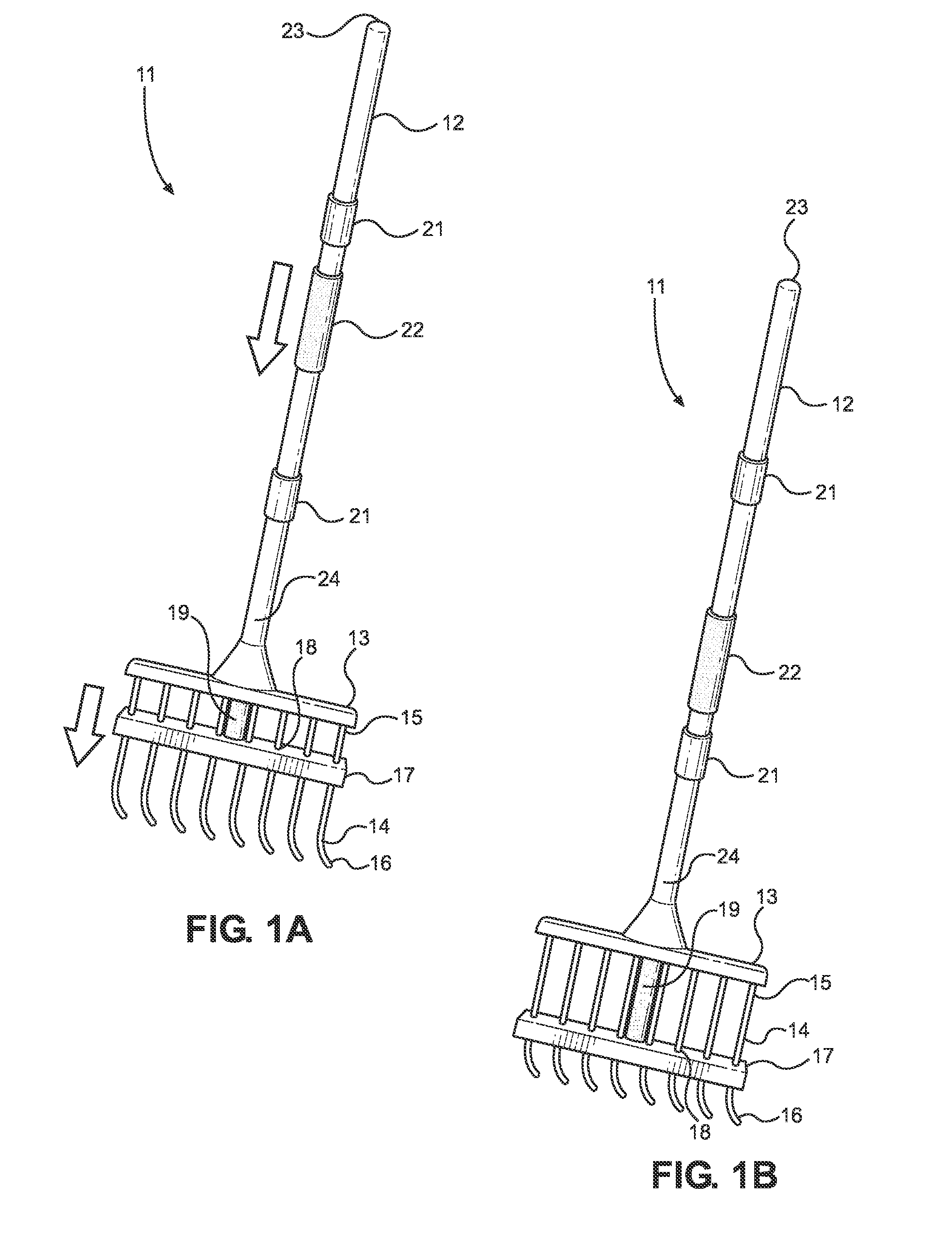
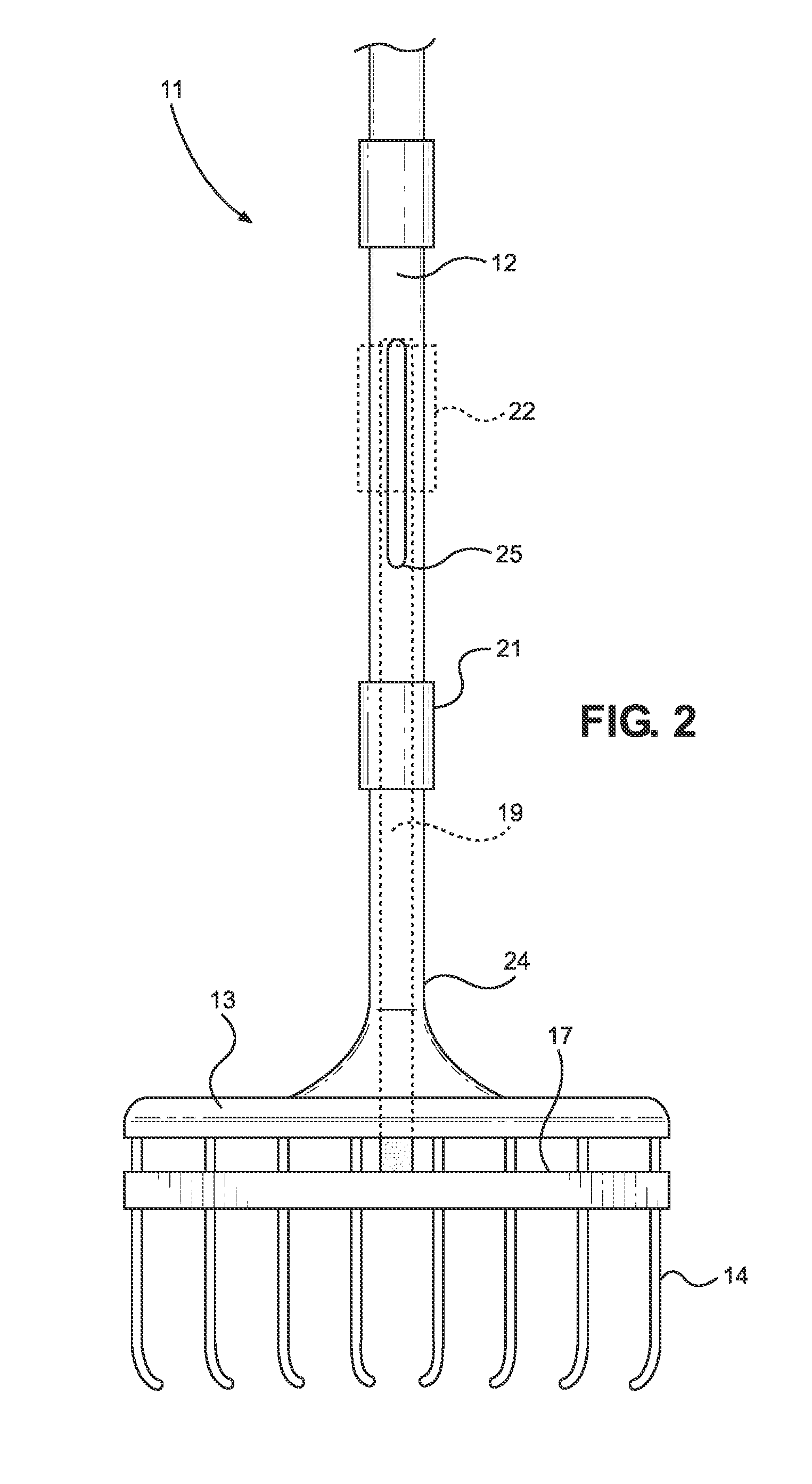
[0032]Referring now to FIGS. 1A and 1B, there are shown views of the self-cleaning rake of the present invention wherein the cleaning bar is in a retracted and extended position, respectively. The self-cleaning rake 11 comprises an elongated shaft 12 having a first end 23 and a second end 24. The elongated shaft 12 includes a hollow interior volume, and preferably comprises a circular cross section.

[0033]A rake head 13 is disposed on the second end 24 of the elongated shaft 12. The rake hea...


PUM


Abstract

Disclosed is a self-cleaning rake. The rake includes an elongated shaft having a rake head on one end thereof. The rake head includes a plurality of elongated tines that can be used to rake leaves and other debris. A cleaning bar is slidably disposed on the tines and can be moved from the first end of the tines towards the second end in order to remove debris lodged between the tines. An extension rod is secured at a first end to the cleaning bar and extends through the rake head and into the interior of the elongated shaft of the self-cleaning rake. A grip is slidably positioned on the exterior of the shaft and is operably connected to the extension rod, such that moving the grip moves the cleaning bar along the tines. The extension rod may be spring-loaded so that the extension rod automatically retracts when extended.

Description

CROSS REFERENCE TO RELATED APPLICATION[0001]This application claims the benefit of U.S. Provisional Application No. 61 / 952,253 filed on Mar. 13, 2014. The above identified patent application is herein incorporated by reference in its entirety to provide continuity of disclosure.BACKGROUND OF THE INVENTION[0002]1. Field of the Invention[0003]The present invention relates to a self-cleaning rake adapted to remove leaves and debris from the tines thereof. More specifically, the present invention provides a rake having an elongated shaft and a rake head having a plurality of tines thereon, wherein a cleaning bar is disposed on the tines and can be moved along the tines in order to remove debris thereon. The cleaning bar can be moved along the tines by actuating a grip disposed on the shaft of the rake and operably connected to the cleaning bar by means of an extension rod disposed within the elongated shaft.[0004]Leaves and other debris often gather in yards, lawns, and other areas. Thi...

Claims


Application Information

Patent Timeline
IPC IPC(8): A01D7/10
CPCA01D7/10
Inventor RIGGS, DONALDRIGGS, CRISTINA
Owner RIGGS DONALD
Why Eureka
Try Eureka