Flow path structure, liquid ejecting head, and liquid ejecting apparatus
a flow path and liquid ejector technology, applied in the direction of printing, inking apparatus, etc., can solve the problems of difficult to reduce the size of the liquid ejector head, and the difficulty of reducing the size of the liquid flow path
- Summary
- Abstract
- Description
- Claims
- Application Information
AI Technical Summary
Benefits of technology
Problems solved by technology
Method used
Image
Examples
second embodiment
[0114]A second embodiment according to the invention is described. The reference sign used in the first embodiment is attached to an element which has the same action or function as in the first embodiment according to each embodiment to be described later and thus, detailed description thereof is appropriately omitted.
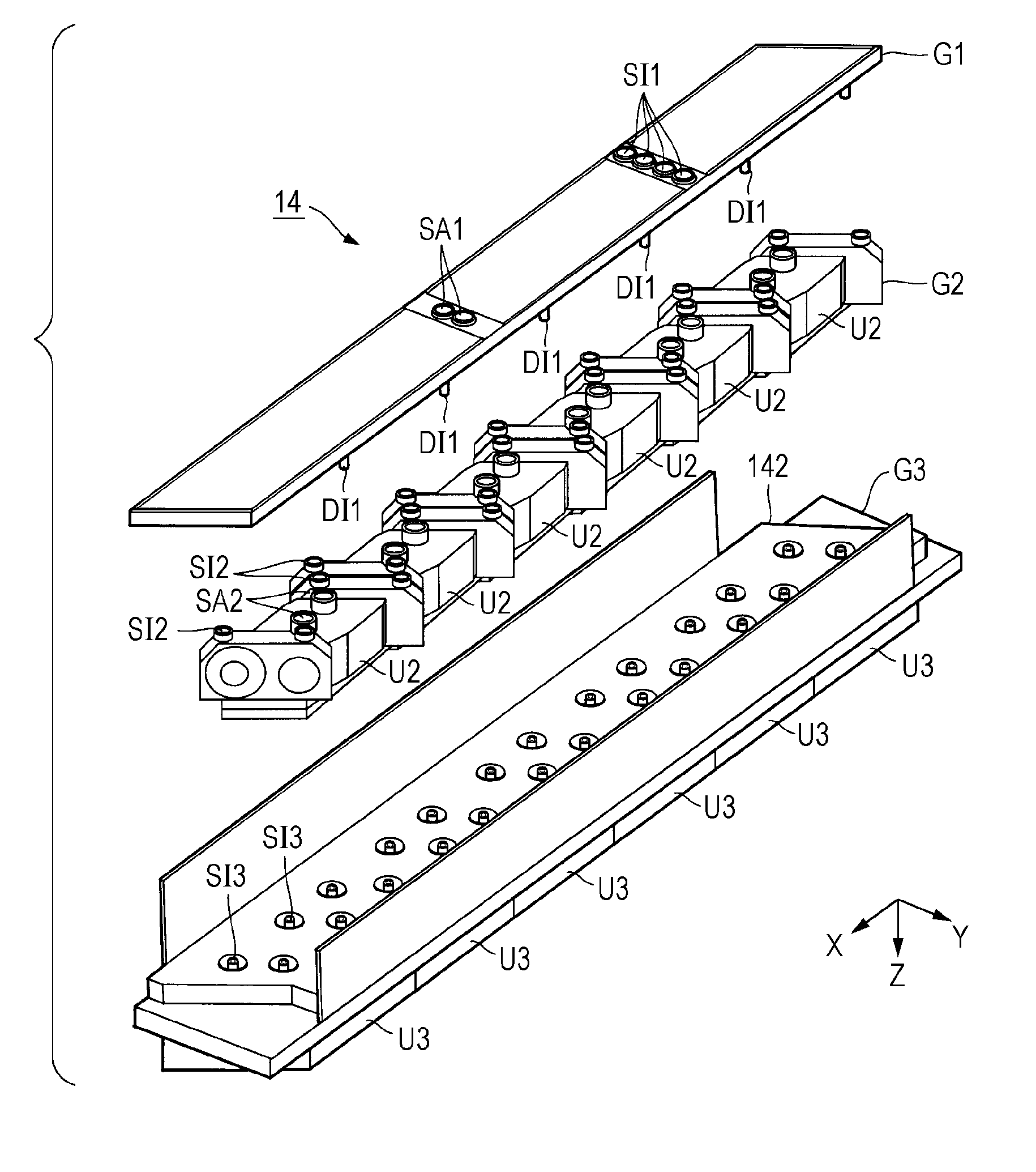
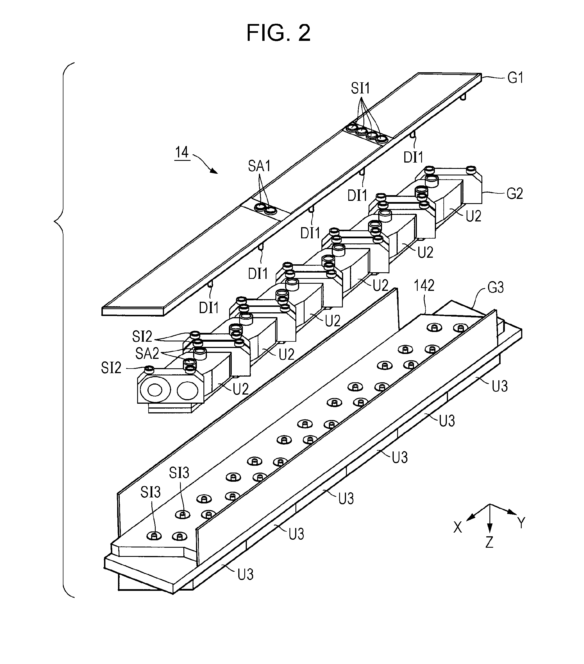
[0115]FIG. 16 illustrates side and plan views of the flow path structure G1 according to a second embodiment. According to the first embodiment, the height of each of the circular tube-shaped discharge ports (DI1 and DA1) formed on the second surface 22 is the same. On the second surface 22 of the flow path structure G1 according to the second embodiment, a plurality of types of discharge ports with different heights from each other are formed on the second surface 22. Specifically, as illustrated in FIG. 16, a height hA of the discharge port DA1 of air A is greater than a hI of the discharge port DI1 of each of the inks I. It is possible to employ a configuration in ...
third embodiment
[0118]FIG. 17 illustrates side and plan views of the flow path structure G1 according to a third embodiment. FIG. 18 is a cross-sectional view (cross section parallel to the X-Z plane) taken along line XVIII-XVIII in FIG. 17. According to the first embodiment, the flow path structure G1 is described, which has a structure in which the film-like sealing portions 25 and the sealing portions 26 are bonded on the substrate 20. As illustrated in FIG. 17, the flow path structure G1 according to the third embodiment is a flat plate-shaped structure which is joined in a state in which the first substrate 27 and the second substrate 28 face each other. The first substrate 27 and the second substrate 28 are flat plate-like members which are long in the X direction similar to the substrate 20 according to the first embodiment is are formed of a thermoplastic resin material such as polypropylene. The first substrate 27 has a first surface 271 on a side opposite to the second substrate 28 and a ...
modification example
[0127]The embodiments described above can be modified in various ways. The aspects of the specific modifications are described as follows. Two or more aspects selected arbitrarily from the following examples can be appropriately combined within a range in which the selected aspects are not incompatible with each other.
[0128](1) According to each embodiment described above, the flow path structure G1 distributes both the ink I and the air A; however, it is possible to use the flow path structure G1 for distributing either one of the ink I or the air A. That is, either the flow path PI1 for distributing the ink I or the flow path PA1 for distributing the air A can be omitted. In addition, according to each embodiment, the flow path controlling section G2 is disposed between the flow path structure G1 and the liquid ejecting section G3; however, a configuration in which the flow path controlling section G2 is omitted or a configuration in which the flow path controlling section G2 is d...
PUM
 Abstract
Description
Claims
Application Information
 - R&D
- Intellectual Property
- Life Sciences
- Materials
- Tech Scout
- Unparalleled Data Quality
- Higher Quality Content
- 60% Fewer Hallucinations
Browse by: Latest US Patents, China's latest patents, Technical Efficacy Thesaurus, Application Domain, Technology Topic, Popular Technical Reports.
© 2025 PatSnap. All rights reserved.Legal|Privacy policy|Modern Slavery Act Transparency Statement|Sitemap|About US| Contact US: help@patsnap.com


