Logical data flow mapping rules for (SUB) graph isomorphism in a cluster computing environment

a cluster computing and logical data flow technology, applied in computing, semi-structured data mapping/conversion, instruments, etc., can solve the problems of programming languages that cannot determine structural compatibility or isolate structural components of cluster computing systems, and the abstractness of programming tools available is not enough to account for all possible permutations of resources

Active Publication Date: 2015-09-17
CONCURRENT
View PDF10 Cites 42 Cited by
  • Summary
  • Abstract
  • Description
  • Claims
  • Application Information

AI Technical Summary

Benefits of technology

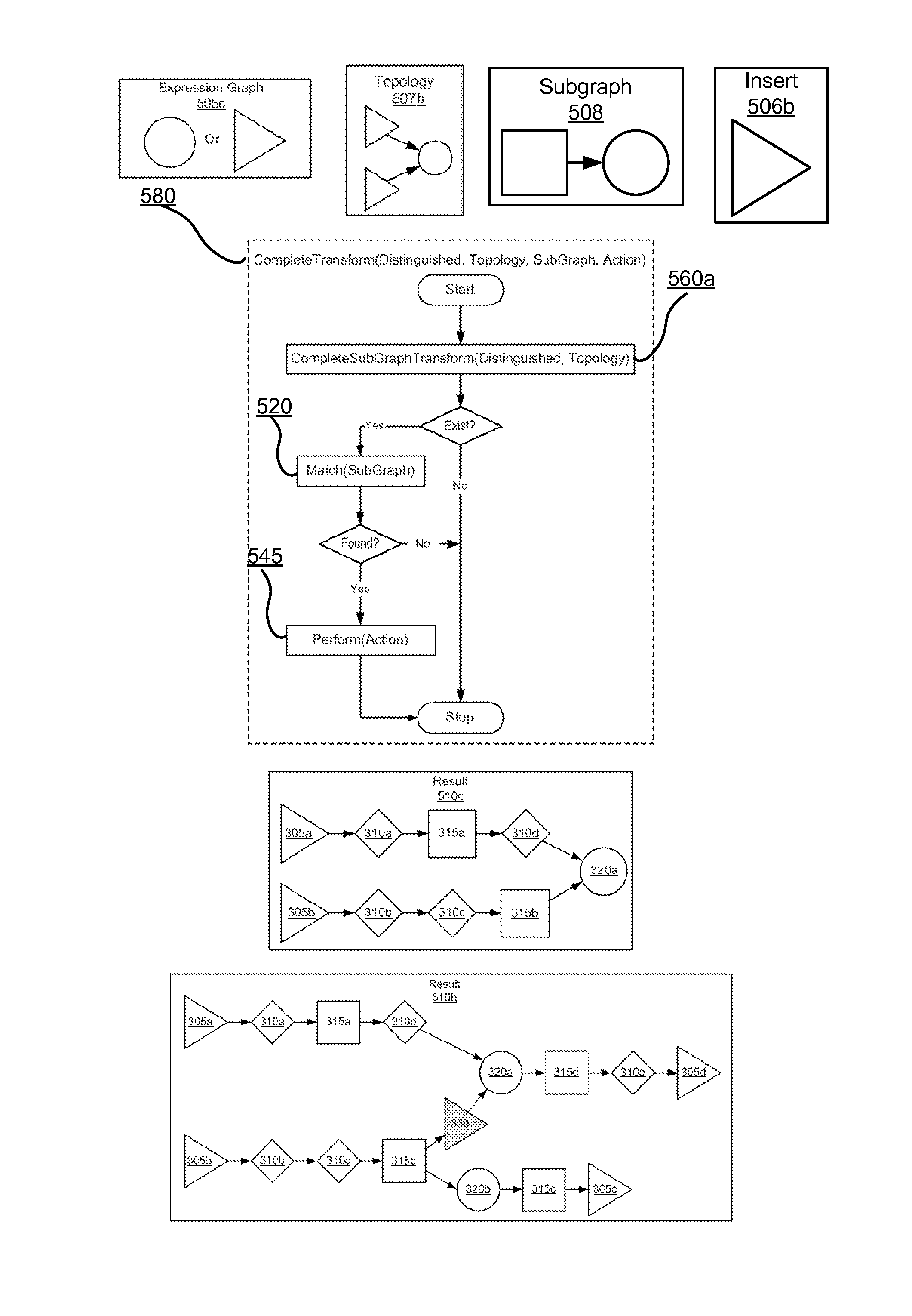
[0007]One way to map a complex, computationally intensive, logical data flow to the resources of cluster computing system is through the use of directed acyclic graphs. A directed acyclic graph is comprised of nodes, and edges that represent the logical data flow to be mapped to a cluster computing system. A node may be a computing device, or server that represents a data source (e.g. producer), data sink (e.g. consumer), a data processing operation, or meta-data (e.g. head, tail, split, join, or combinations thereof) within the cluster computing system. Edges represent computational paths that connect two or more nodes and include ordinal, cardinal, or directional meta-data that describe movement of cluster system data in relation to a node. Logical data flow cannot be executed directly; it only represents a definition of the work to transform data and other resources on a cluster computing system. To be executed across a cluster of network connected computing devices, the logical data flow is compatibly mapped onto the available infrastructure resources of the target cluster. Computing devices perform a portion of the data flow but have varying capabilities, and may need to be configured appropriately to support their portion of logical data flow processing.

Problems solved by technology

This environment presents a challenge for designers seeking to implement a write-once repetitive use application that is portable across different cluster computing systems.
Programming tools available aren't abstract enough to account for all possible permutations of resources in cluster computing systems.
Additionally, programming languages cannot determine structural compatibility or isolate structural components of cluster computing systems.
Current programming tools present challenges for implementing identical functionality reliably across different cluster platforms.

Method used


Image

  • Logical data flow mapping rules for (SUB) graph isomorphism in a cluster computing environment
  • Logical data flow mapping rules for (SUB) graph isomorphism in a cluster computing environment
  • Logical data flow mapping rules for (SUB) graph isomorphism in a cluster computing environment

Examples


Embodiment Construction

[0017]The Figures (FIGS.) and the following description relate to preferred embodiments by way of illustration only. It should be noted that from the following discussion, alternative embodiments of the structures and methods disclosed herein will be readily recognized as viable alternatives that may be employed without departing from the principles of what is claimed.

[0018]Reference will now be made in detail to several embodiments, examples of which are illustrated in the accompanying figures. It is noted that wherever practicable similar or like reference numbers may be used in the figures and may indicate similar or like functionality. The figures depict embodiments of the disclosed system (or method) for purposes of illustration only.

[0019]One skilled in the art will readily recognize from the following description that alternative embodiments of the structures and methods illustrated herein may be employed without departing from the principles described herein.

Cluster Computin...


PUM


Abstract

A system and a method are disclosed for transforming cluster computing resources of a target system to match a user defined logical data flow so data processing between the source and target are functionally equivalent. The source logical dataflow is compatibly mapped to a target directed acyclic graph that represents the cluster computing resources. A series of subgraph assertion and transform operations are applied iteratively until the logical data flow is isomorphic with a directed acyclic graph. The assertion and transform operations are comprised of rules and assertions, which are maintained in a rules registry.

Description

CROSS-REFERENCE TO RELATED APPLICATIONS[0001]This application claims the benefit of U.S. Provisional Application No. 61 / 953,324, filed Mar. 14, 2014 which is hereby incorporated herein by reference.BACKGROUND[0002]1. Field of Art[0003]The disclosure generally relates to the field of cluster computing in particular to the mapping of a logical data flow to a directed acyclic graph representative of a cluster computer system.[0004]2. Description of the Related Art[0005]Cluster computing includes multiple self-contained computing devices working sequentially or in parallel as a unified system. The computing devices interact with each other via a network to solve a common problem that can be divided into many smaller, manageable problems. For example, cluster computing systems are currently employed to process big data problem sets relating to healthcare, genomics, or social networking services. Logical data flow processing is well-suited for defining these problems in a cluster computin...

Claims


Application Information

Patent Timeline
Patent Type & Authority Applications(United States)
IPC IPC(8): G06F17/30
CPCG06F17/30958G06F17/30914G06F9/4494G06F16/9024G06F16/84
Inventor WENSEL, CHRIS K.
Owner CONCURRENT
Why Eureka
Try Eureka