Cattle Hoof Trimming Chute

a hoof trimming and chute technology, applied in the field of restraining chutes, can solve the problems of insufficient walking or roaming of domesticated livestock, natural wear of hoofs, and inability of the person operating the control to see the head of the animal, etc., and achieve the effect of convenient operation and easy trimming

Inactive Publication Date: 2015-09-24
BEAVERS BRANDON
View PDF17 Cites 3 Cited by
  • Summary
  • Abstract
  • Description
  • Claims
  • Application Information

AI Technical Summary

Benefits of technology

[0018]There are four cattle leg latches located on the bottom of the chute, one for each cow leg. The legs are secured by means of the leg latches, and the cow is now in position so that its hooves can be easily trimmed by a single hoof trimmer. The leg latches are hydraulically controlled, and manipulated by a hand held remote control device so that the trimmer can hold a leg in one hand and easily operate the remote control to close the latch with the other hand.
[0019]There is a staging at the rear of the chute. The staging area consists of a three-sided pen that prevents waiting animals from getting in the way of the operator and the moving components of the chute, particularly the tail gate, which swings down behind the rear of the chute. The staging area allows the hoof trimmer or operator to manage the movement of the an...

Problems solved by technology

In some situations the animal walks enough so that the hooves are naturally worn down.
But domesticated livestock typically do not walk or roam sufficiently, and in many cases their hooves need to be trimmed on occasion for the health and well being of the animal.
Modern layover hoof trimming chutes make trimming cattle hooves relatively easy, and while all of the prior art chutes have advantages, they also have disadvantages.
But the Riley patent places the hydraulic controls at the rear of the chute, which means the person operating the controls cannot see the head of the animal is it nears and extends from the front gate.
The problem occurs when the leg is released in order to tie the rope or secure the chain.
The other pr...

Method used


Image

  • Cattle Hoof Trimming Chute
  • Cattle Hoof Trimming Chute
  • Cattle Hoof Trimming Chute

Examples


Embodiment Construction

[0041]Detailed embodiments of the present invention are disclosed herein. It is to be understood that the disclosed embodiments are merely exemplary of the invention, and that there may be a variety of other alternate embodiments. The figures are not necessarily to scale, and some features may be exaggerated or minimized to show details of particular components. Therefore, specified structural and functional details disclosed herein are not to be interpreted as limiting, but merely as a basis for teaching one skilled in the art to employ the varying embodiments of the present invention.

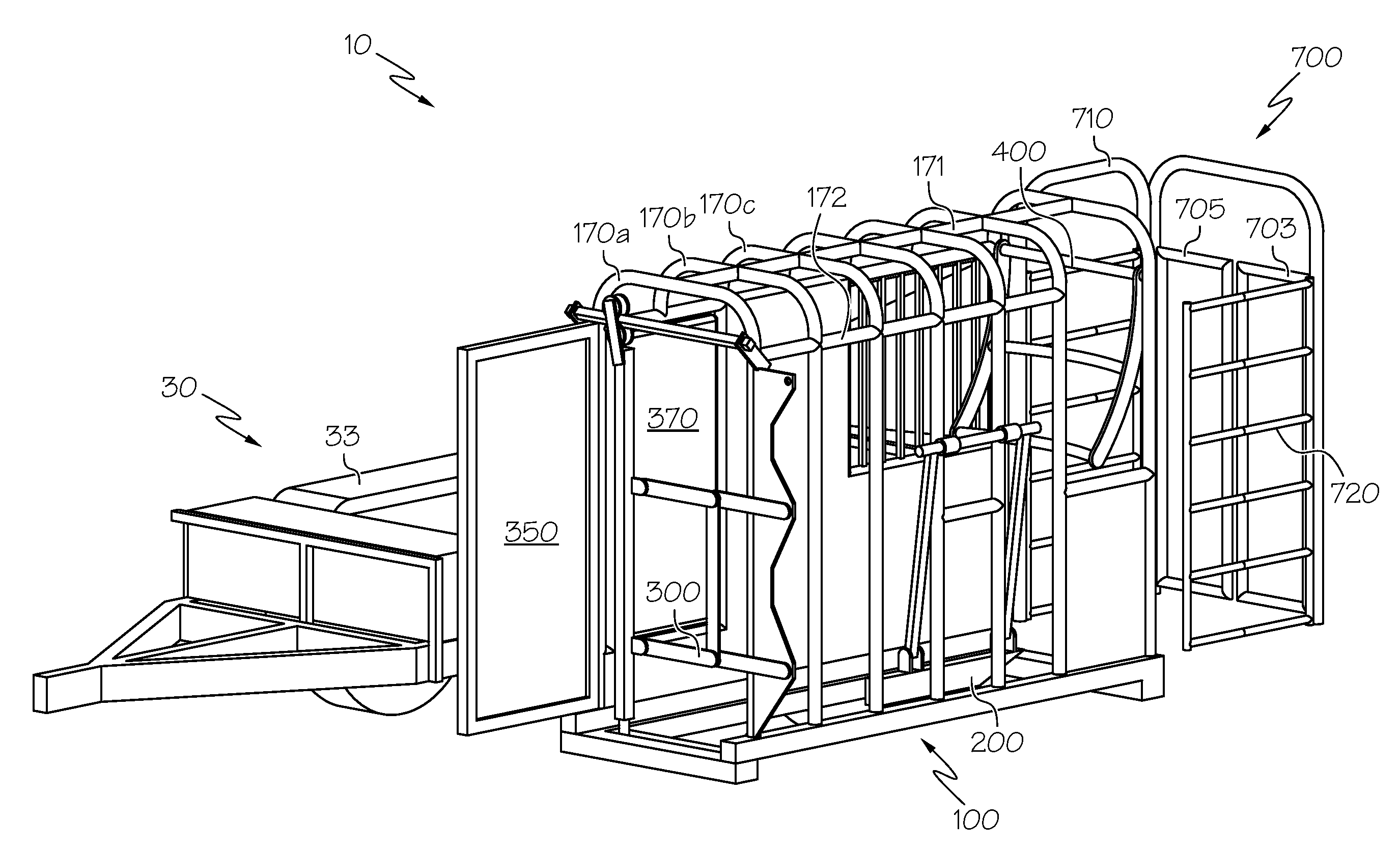
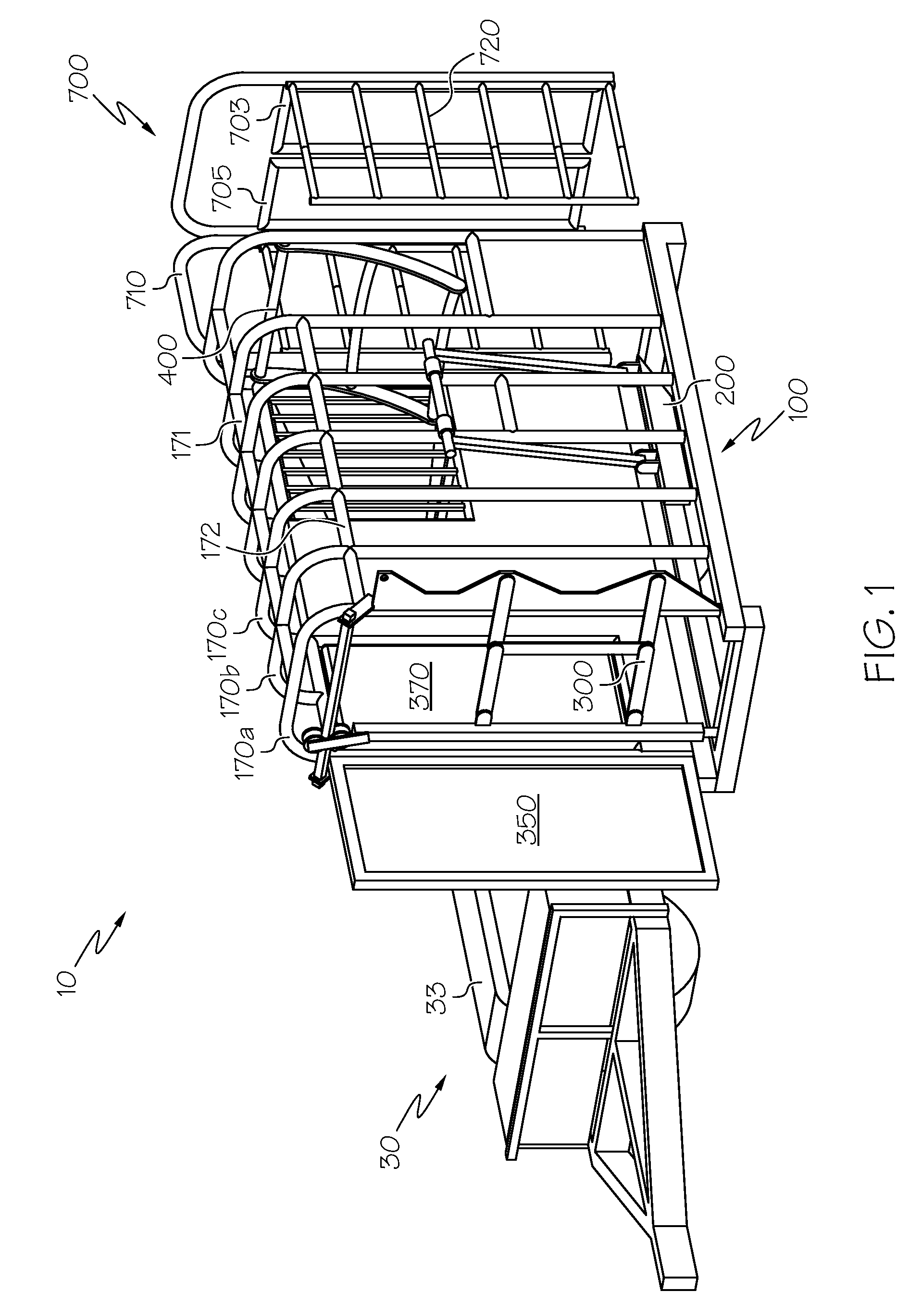
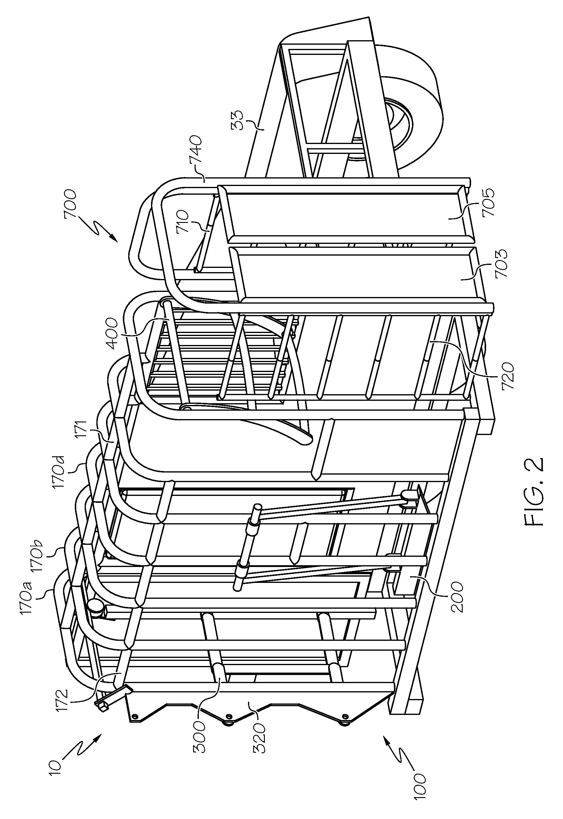
[0042]The present invention is a layover chute for restraining an animal for the purposes of trimming its hooves. The teachings of this invention can be applied for restraining chutes used for other types of animals, and for other purposes, such as medical inspection or treatment, but in the preferred embodiment the invention is a chute for trimming the hooves of cattle. The chute of the present inven...


PUM


Abstract

An animal restraining chute having a four sided cage with a closeable front and rear opening and two sides constructed from a series of ribs made from a single bent component to provide structural support. A partially closable front gate closes the front opening and restrains the head of the animal, and a curved rear pusher gate secures the hindquarters of an animal. A rotatable belly restraint pins the animal to one of the sides. The chute is rotatably mounted on a vehicle or platform to lay the animal on its side. The chute includes four hydraulic activated leg latches for securing the legs of the animal. There is a movably attached staging area located at the rear of the chute to allow for the positioning of animals waiting to enter the chute. Each of the movable components of the chute are hydraulically and remotely controlled.

Description

CROSS REFERENCE TO RELATED APPLICATIONS[0001]This application claims priority to U.S. Provisional Patent Application No. 61 / 968,803 filed on Mar. 21, 2014, and U.S. Provisional Patent Application No. 61 / 969,514 filed Mar. 24, 2014. The teachings of both provisional applications are fully incorporated herein.STATEMENT REGARDING FEDERALLY SPONSORED RESEARCH OR DEVELOPMENT[0002]Not Applicable.THE NAMES OF THE PARTIES TO A JOINT RESEARCH AGREEMENT[0003]Not Applicable.INCORPORATION-BY-REFERENCE OF MATERIAL SUBMITTED ON A COMPACT DISC[0004]Not Applicable.BACKGROUND OF THE INVENTION[0005]1. Field of the Invention[0006]The present invention relates to a restraining chute for holding animals for the purpose of veterinary and other inspection, and for trimming the hooves of animals such as cattle. The present invention is a fully automated chute that restrains the animal, lays it on its side, and secures its legs for inspection and trimming of the hooves.[0007]2. Description of the Related Ar...

Claims


Application Information

Patent Timeline
IPC IPC(8): A01K1/06
CPCA01K1/0613A61D2003/006A61D2003/003A01L13/00A61D3/00
Inventor BEAVERS, BRANDON
Owner BEAVERS BRANDON
Why Eureka
Try Eureka