Image forming apparatus

a technology of forming apparatus and forming roller, which is applied in the direction of gearing, thin material processing, printing, etc., can solve the problems of insufficient deflection prevention, insufficient deflection, and insufficient deflection, so as to reduce or prevent the deformation (deflection) of the feeding roller, reduce or prevent the deterioration of the sheet feeding accuracy, and stabilize the belt condition

Inactive Publication Date: 2015-09-24
FUNAI ELECTRIC CO LTD
View PDF6 Cites 3 Cited by
  • Summary
  • Abstract
  • Description
  • Claims
  • Application Information

AI Technical Summary

Benefits of technology

[0010]The image forming apparatus preferably further includes a tension applying member including a rotatable member that presses the belt and is rotatable together with movement of the belt, the tension applying member being configured to apply tension to the belt, wherein the biasing member is configured to bias the feeding roller in a direction opposite to a direction of deformation of the feeding roller caused by the tension applied to the belt by the tension applying member. This configuration stabilizes the belt conditions using the tension applying member. Furthermore, a first moment applied by the belt, to which the tension has been added by the tension applying member, and a second moment applied to the feeding roller by the biasing member cancel each other. Thus, it is possible to further effectively reduce or prevent the deformation (deflection) of the feeding roller. As a result, it is possible to further reduce or prevent the deterioration of sheet feeding accuracy.
[0011]The feeding roller is preferably made of resin and integrally includes a roller configured to abut the sheet, and a shaft provided at each end of the roller and biased by the biasing member. In the case of a feeding roller made of resin, which is easily deformed, using the biasing member according to a preferred embodiment of the present invention is particularly effective to reduce or prevent the deformation of the feeding roller caused by the belt.
[0012]The belt rotating mechanism preferably includes a sheet supply roller configured to supply a sheet from the upstream of the feeding roller, the belt being disposed across the sheet supply roller and the feeding roller, the sheet supply roller is

Problems solved by technology

Disadvantageously, therefore, deflection occurs in the feeding roller at an area where no deflection prevention member is arranged.
Thus, the deflection prevention member described in JP 2006-34988

Method used


Image

  • Image forming apparatus
  • Image forming apparatus
  • Image forming apparatus

Examples


first preferred embodiment

[0025]A configuration of an inkjet printer 100 according to a first preferred embodiment of the present invention will be described with reference to FIGS. 1 to 5. The inkjet printer 100 is an example of an “image forming apparatus” according to a preferred embodiment of the present invention.

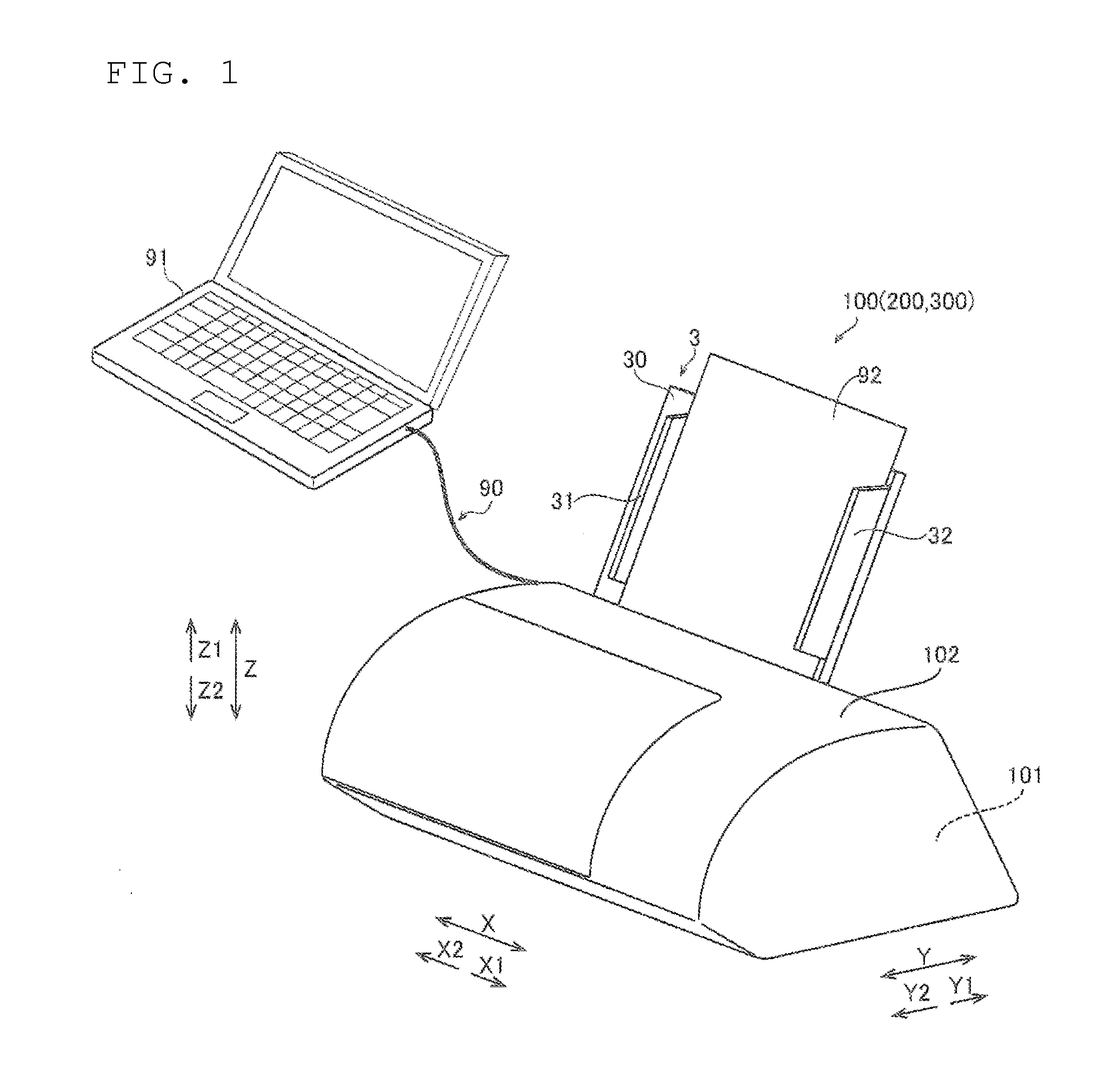
[0026]As shown in FIG. 1, the inkjet printer 100 includes a main body 101 and a cover 102 that covers the main body 101.

[0027]The inkjet printer 100 is connected, for example, to a personal computer (PC) 91 via a USB cable 90, but can also be connected wirelessly. The inkjet printer 100 is configured to operate in response to user operations on the PC 91 connected to the inkjet printer 100. In use, the inkjet printer 100 is placed so that a front side (Y2 direction side) thereof faces the user. Here, the “front side” in the present preferred embodiment represents a side facing the user of the inkjet printer 100 during normal use.

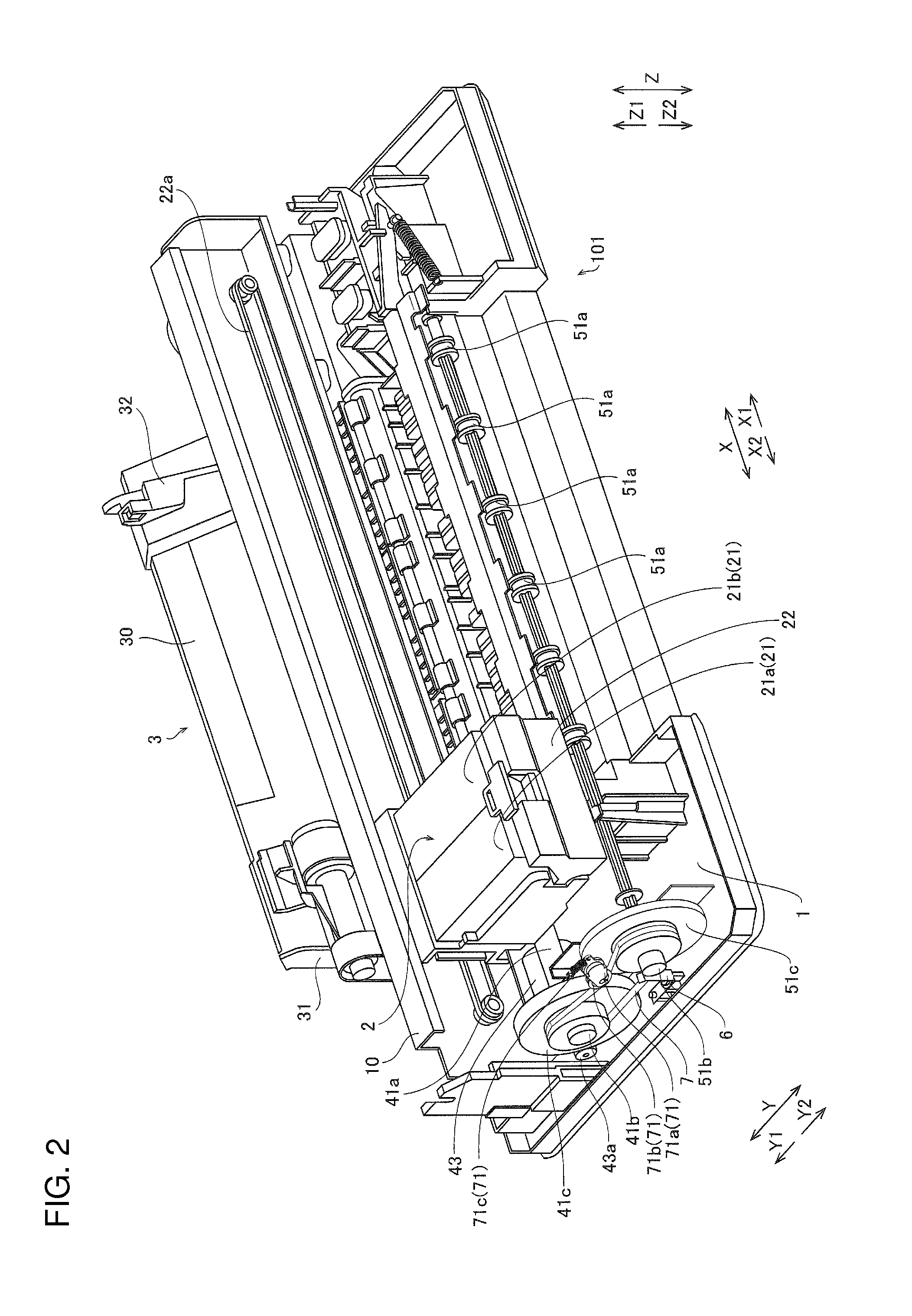
[0028]As shown in FIG. 2, the main body 101 of the inkjet printer ...

second preferred embodiment

[0055]A configuration of an inkjet printer 200 according to a second preferred embodiment of the present invention will be described with reference to FIGS. 1 and 6. The second preferred embodiment describes an example of biasing a lower feeding roller 51 using a wire spring 206, unlike the first preferred embodiment that uses the leaf spring 6 to bias the lower feeding roller 51. The inkjet printer 200 is an example of an “image forming apparatus” according to a preferred embodiment of the present invention. The wire spring 206 is an example of a “biasing member” according to a preferred embodiment of the present invention. For a similar configuration to the first preferred embodiment, description will be omitted by using the same reference signs as in the first preferred embodiment, attached to the figures.

[0056]As shown in FIG. 6, the inkjet printer 200 (see FIG. 1) according to the second preferred embodiment includes the wire spring 206.

[0057]The wire spring 206 is fixedly atta...

third preferred embodiment

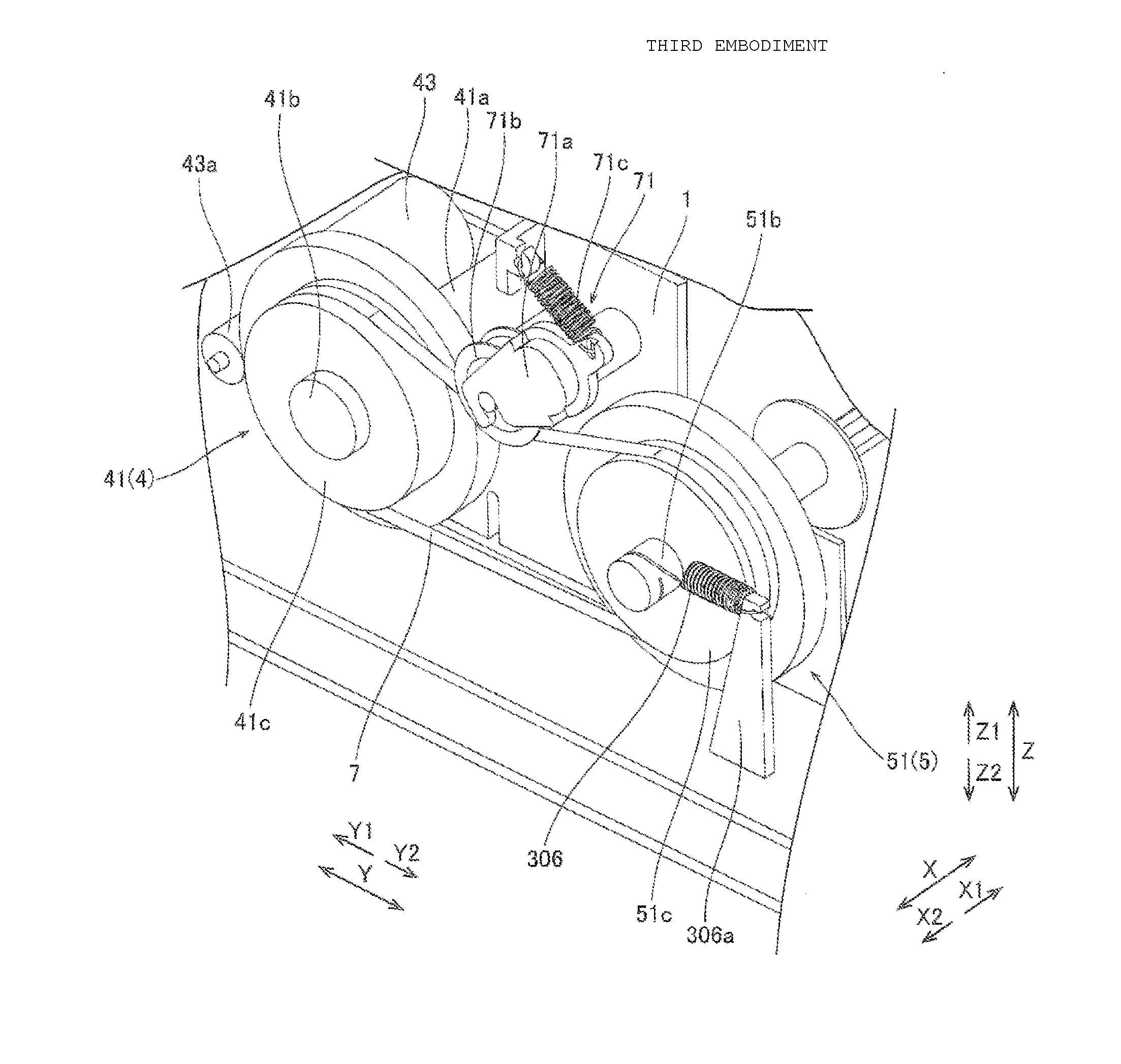
[0065]A configuration of an inkjet printer 300 according to a third preferred embodiment of the present invention will be described with reference to FIGS. 1 and 7. The third preferred embodiment describes an example of biasing a lower feeding roller 51 using an extension coil spring 306, unlike the first preferred embodiment that preferably uses the leaf spring 6 to bias the lower feeding roller 51. The inkjet printer 300 is an example of an “image forming apparatus” according to a preferred embodiment of the present invention. The extension coil spring 306 is an example of a “coil spring” and a “biasing member” according to a preferred embodiment of the present invention. For a similar configuration to the first preferred embodiment, description will be omitted by using the same reference signs as in the first preferred embodiment, attached to the figures.

[0066]As shown in FIG. 7, the inkjet printer 300 (see FIG. 1) according to the third preferred embodiment includes the extensio...


PUM


Abstract

An image forming apparatus includes a printer, a lower feeding roller that feeds a sheet, a bearing that rotatably supports the lower feeding roller with respect to a housing, a belt rotating mechanism including a belt disposed over the lower feeding roller and driving the lower feeding roller, and a leaf spring that biases the lower feeding roller in a direction opposite to the direction of deformation of the feeding roller caused by the tension of the belt. The belt is arranged on the outer side in the axial direction of the lower feeding roller with respect to the bearing. The leaf spring is arranged on the outer side in the axial direction of the lower feeding roller with respect to the belt, so that the leaf spring biases the lower feeding roller.

Description

BACKGROUND OF THE INVENTION[0001]1. Field of the Invention[0002]The present invention relates to an image forming apparatus, and particularly to an image forming apparatus including a belt.[0003]2. Description of the Related Art[0004]An image forming apparatus including a belt is known in the related art, as disclosed in JP 2006-349883 A.[0005]JP 2006-349883 A discloses an image forming apparatus including a printing unit, a feeding roller to feed a sheet, a belt disposed across substantially the whole area in the axial direction of the feeding roller, and a belt stretching roller that rotates with the feeding roller after the belt is arranged and a driving force is applied to the feeding roller. The above image forming apparatus also includes a deflection prevention member configured to control deflection of the feeding roller and the belt stretching roller caused by the tension of the belt. The deflection prevention member is arranged at the substantially central position in the a...

Claims


Application Information

Patent Timeline
IPC IPC(8): B65H5/06B65H7/20F16H7/08
CPCB65H5/064B65H7/20F16H7/08F16H2007/0808B41J13/03B65H5/06B65H2404/16B65H2404/17
Inventor TAKAGI, MASAAKIEMI, YOHEI
Owner FUNAI ELECTRIC CO LTD
Why Eureka
Try Eureka