Eureka AIR delivers breakthrough ideas for toughest innovation challenges, trusted by R&D personnel around the world.

Synchronous moving double-axis hinge

a double-axis hinge and synchronous technology, applied in the field of double-axis hinges, can solve the problems of shortening the life of spur gears or bevel gears, limiting the use angle of electronic devices, and reducing the service life of conventional single-axis hinges, so as to achieve the effect of easy generation of impact and friction

Inactive Publication Date: 2015-09-24
SINHER TECH INC
View PDF7 Cites 53 Cited by
  • Summary
  • Abstract
  • Description
  • Claims
  • Application Information

AI Technical Summary

Benefits of technology

[0005]The primary object of the present invention is to solve the problem of the conventional double-axis hinge that gears easily generate impact and friction between them because of tolerances.
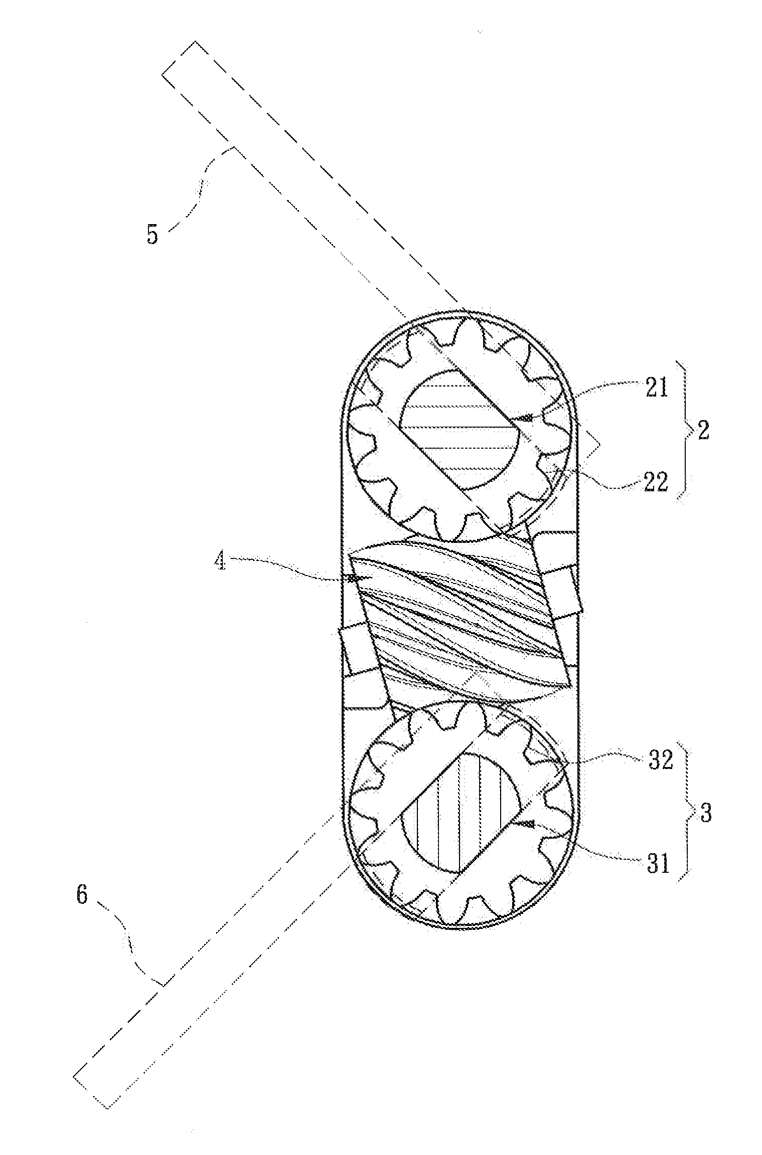
[0016]1. The invention employs crossed helical gears to overcome the problem of the spur gears or bevel gears caused by tolerance in the conventional technique. In the conventional technique, in the event that the axes of the spur gears or bevel gears and the collaborated gears are not parallel to result in eccentricity or the gear teeth are not parallel, the teeth of the gears can only form point contact between them that tends to generate impact and friction between the gear teeth and shorten the lifespan of the spur gears or bevel gears. The crossed helical gears of the invention can overcome the aforesaid flaws by providing curved teeth profile to form close contact between the gear teeth to improve the shortcoming of impact and friction that might otherwise occur.
[0017]2. The invention provides synchronous movements of two shafts through the crossed helical gears. The crossed helical gears have smaller gaps between the helical teeth to provide a shorter idle displacement. Hence before the engaged teeth separate from each other, the next set of teeth are engaged already. Thus the helical teeth of the crossed helical gears can effectively amplify the contact among the gear teeth to provide steadier transmission.

Problems solved by technology

Although it allows the display to be flipped against the body, the display and body interfere with each other when the display has been opened at a certain angle, hence it limits use angle of the electronic device.
As a result, the conventional single-axis hinge no longer meets the present market requirement, so that double-axis hinges have been developed.
However, in the event that the axes of the spur gears or bevel gears and the collaborated gears are not parallel to result in eccentricity or the gear teeth are not parallel, the teeth of the gears can only form point contact between them that tends to generate impact and friction between the gear teeth and shorten the lifespan of the spur gears or bevel gears.
Hence how to improve the double-axis hinge to provide steady transmission is an issue yet to be resolved in the industry.

Method used


Image

  • Synchronous moving double-axis hinge
  • Synchronous moving double-axis hinge
  • Synchronous moving double-axis hinge

Examples


Embodiment Construction

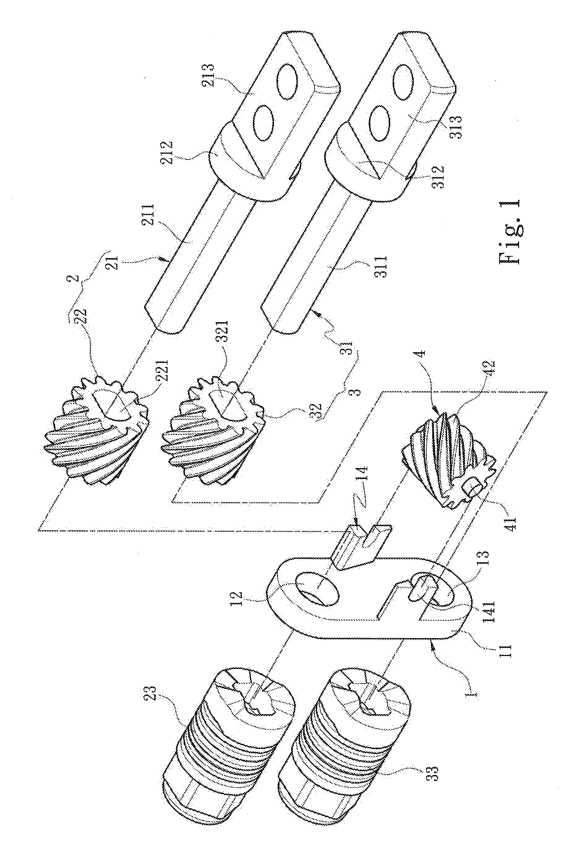
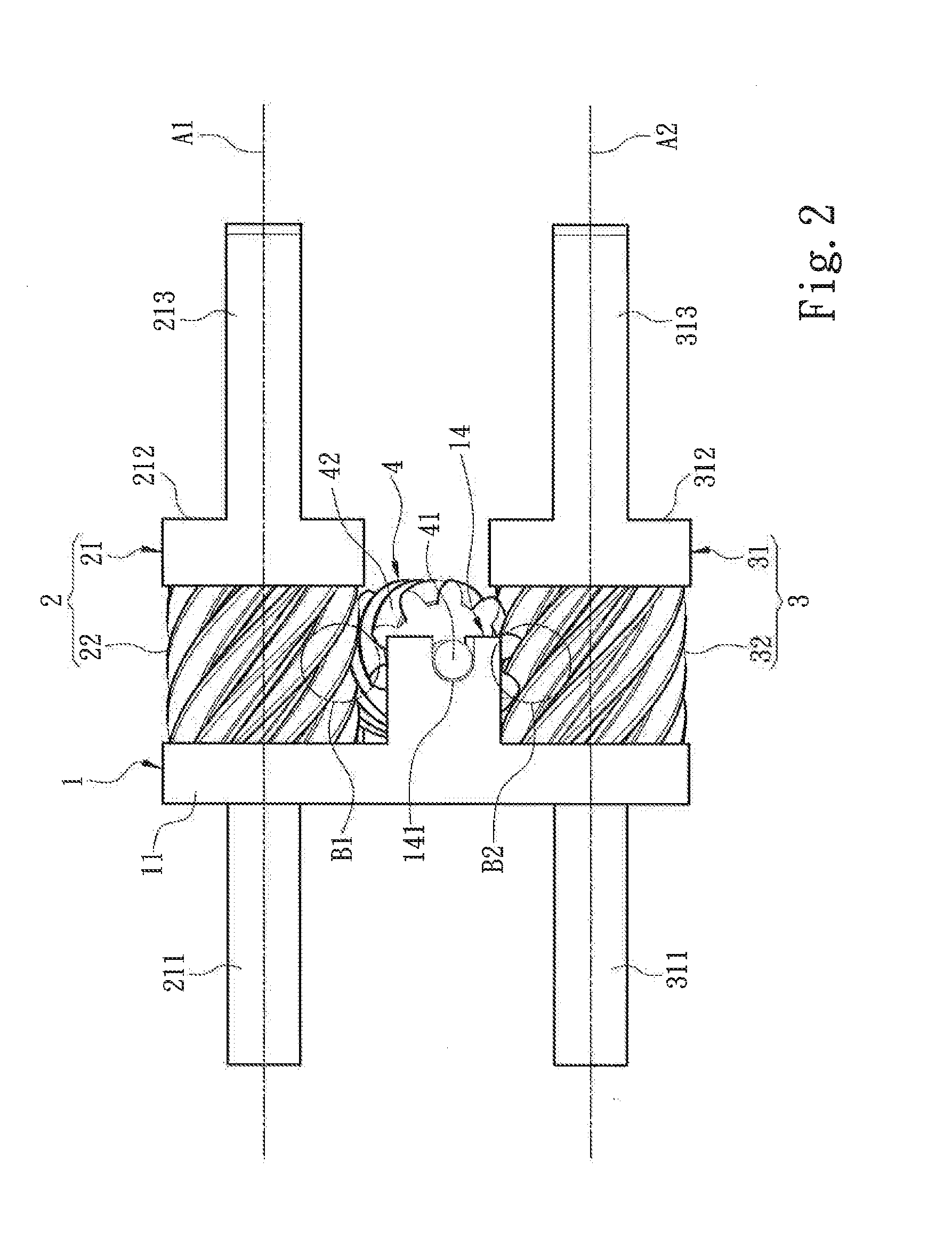
[0024]Please refer to FIG. 1, the present invention aims to provide a synchronous moving double-axis hinge that comprises a support member 1, a first transmitting assembly 2, a second transmitting assembly 3 and a transmission element 4. The support member 1 includes a main body 11, a first hinge hole 12 and a second hinge hole 13 formed on the main body 11, and at least one holding portion 14 located on the main body 11 between the first and second hinge holes 12 and 13. The holding portion 14 has an installation section 141. The first transmitting assembly 2 is mounted on the support member 1, and includes a first transmission shaft 21 hinged in the first hinge hole 12, a first helical gear 22 annularly coupled on the surface of the first transmission shaft 21 and a first torsional force generation portion 23 run through by the first transmission shaft 21 to provide a torsional force required by the first transmission shaft 21. The first transmission shaft 21 also has a first latc...


PUM


Abstract

A synchronous moving double-axis hinge comprises a support member, a first transmitting assembly and a second transmitting assembly mounted onto the support member, and a transmission element installed on the support member. The first transmitting assembly includes a first transmission shaft and a first helical gear. The second transmitting assembly includes a second transmission shaft and a second helical gear. The transmission element includes a hinge pin and a driven helical gear. The driven helical gear has a first engaging zone to engage with the first helical gear and a second engaging zone to engage with the second helical gear. The hinge pin has a third extension axis crossing with a first extension axis of the first transmission shaft and a second extension axis of the second transmission shaft. Thus the crossed helical gears can effectively amplify the contact among the gear teeth to make transmission steadier.

Description

FIELD OF THE INVENTION[0001]The present invention relates to a double-axis hinge and particularly to a synchronous moving double-axis hinge that provides steady opening and closing.BACKGROUND OF THE INVENTION[0002]A conventional flip electronic device such as a notebook computer, mobile phone or the like generally has a hinge to bridge a display and a body to allow the display to be opened or closed against the body, and also provide a torsional force to support and anchor the display at a desired angle after being opened. In the past, the hinge usually was a single-axis hinge with only one shaft as an axis. Although it allows the display to be flipped against the body, the display and body interfere with each other when the display has been opened at a certain angle, hence it limits use angle of the electronic device. Nowadays touch control electronic devices equipped with a keyboard and a touch screen are very popular. Aside from using the keyboard to do input as usual, flipping t...

Claims


Application Information

Patent Timeline
Patent Type & Authority Applications(United States)
IPC IPC(8): E05D11/00E05D3/06
CPCE05D3/06E05D11/00E05D3/122G06F1/1681E05Y2999/00
Inventor CHIANG, YUNG-CHANG
Owner SINHER TECH INC
Why Eureka
Eureka Blog
Learn More