Safety device for a bearing arrangement of a rotor of a turbomachine

a safety device and rotor technology, applied in the direction of sliding contact bearings, machines/engines, electric/magnetic/electromagnetic heating, etc., can solve the problems of high unbalance, damage or even destroy the bearing arrangement of the rotor and other static structures, including the engine mount, and the limit force can only be set very imprecisely, so as to achieve good protection

Active Publication Date: 2015-09-24
MTU AERO ENGINES GMBH
View PDF3 Cites 0 Cited by
  • Summary
  • Abstract
  • Description
  • Claims
  • Application Information

AI Technical Summary

Benefits of technology

[0020]In an advantageous embodiment of the invention, it is provided for the safety device to be arranged in such a way that its buckling structure collapses as soon as the moving rotor experiences a dynamic unbalance that exceeds a predetermined limit value, and/or in such a way that, if the buckling structure has collapsed, it is at least largely prevented that radial loads that exceed a predetermined limit value a

Problems solved by technology

In case of a blade failure in a turbine engine, for example, because of a bird strike or the like, high unbalances occur in the rotor which, in the worst-case scenario, can damage or even destroy the bearing arrangement of the rotor as well as other static structures, including the engine mount.
A main problem of these safety devices, however, is the configuration of the predetermined breaking points since, with such predeterm

Method used


Image

  • Safety device for a bearing arrangement of a rotor of a turbomachine
  • Safety device for a bearing arrangement of a rotor of a turbomachine
  • Safety device for a bearing arrangement of a rotor of a turbomachine

Examples


Embodiment Construction

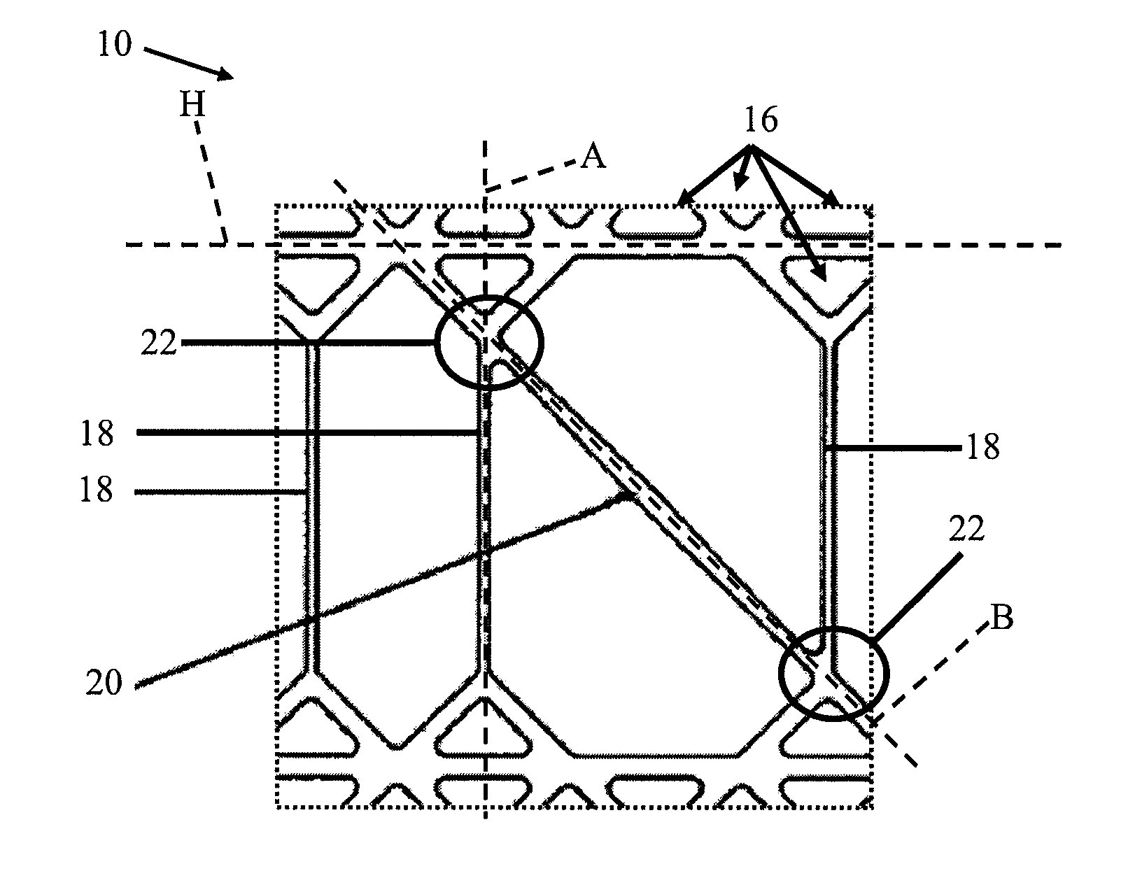
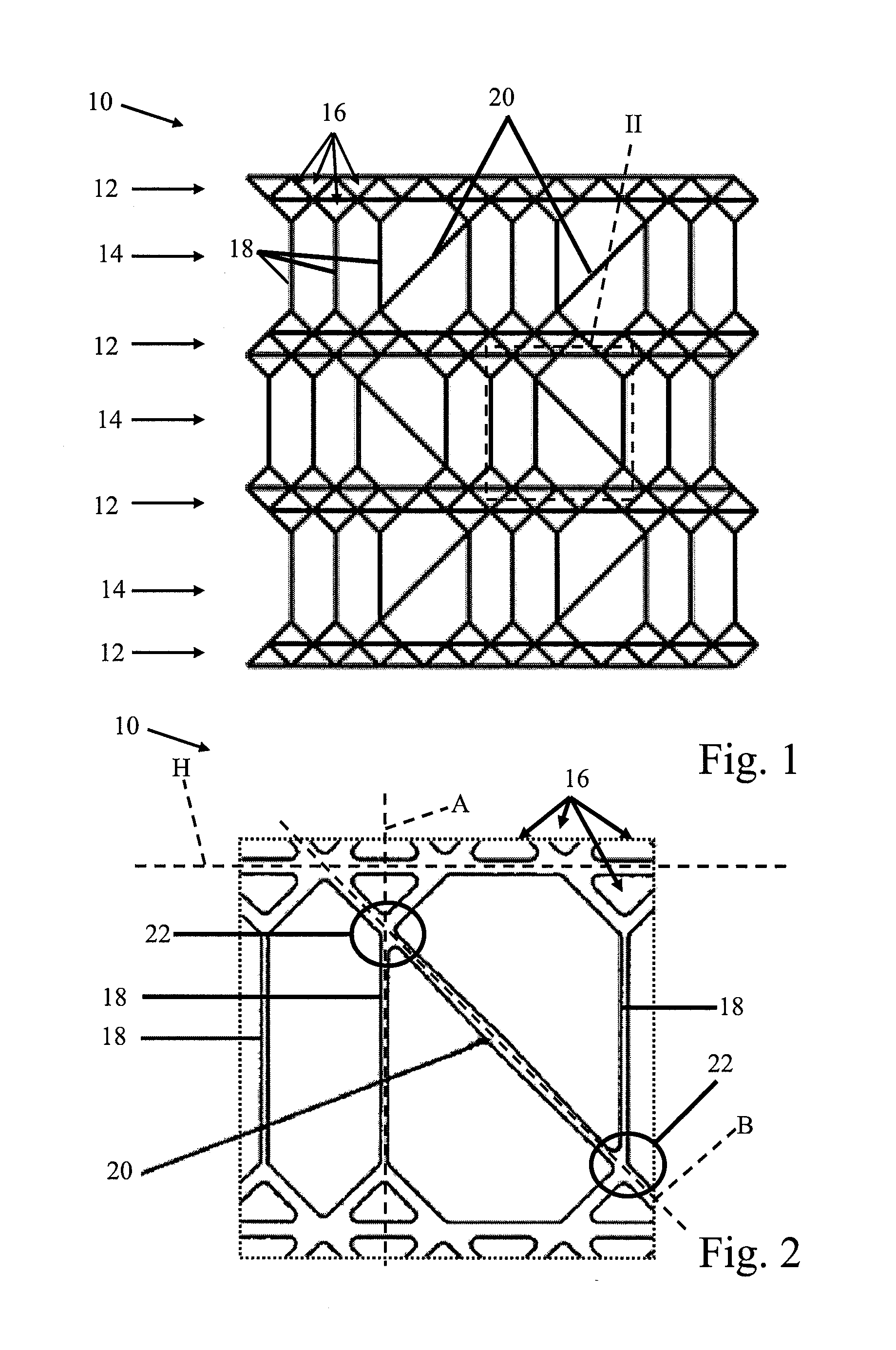
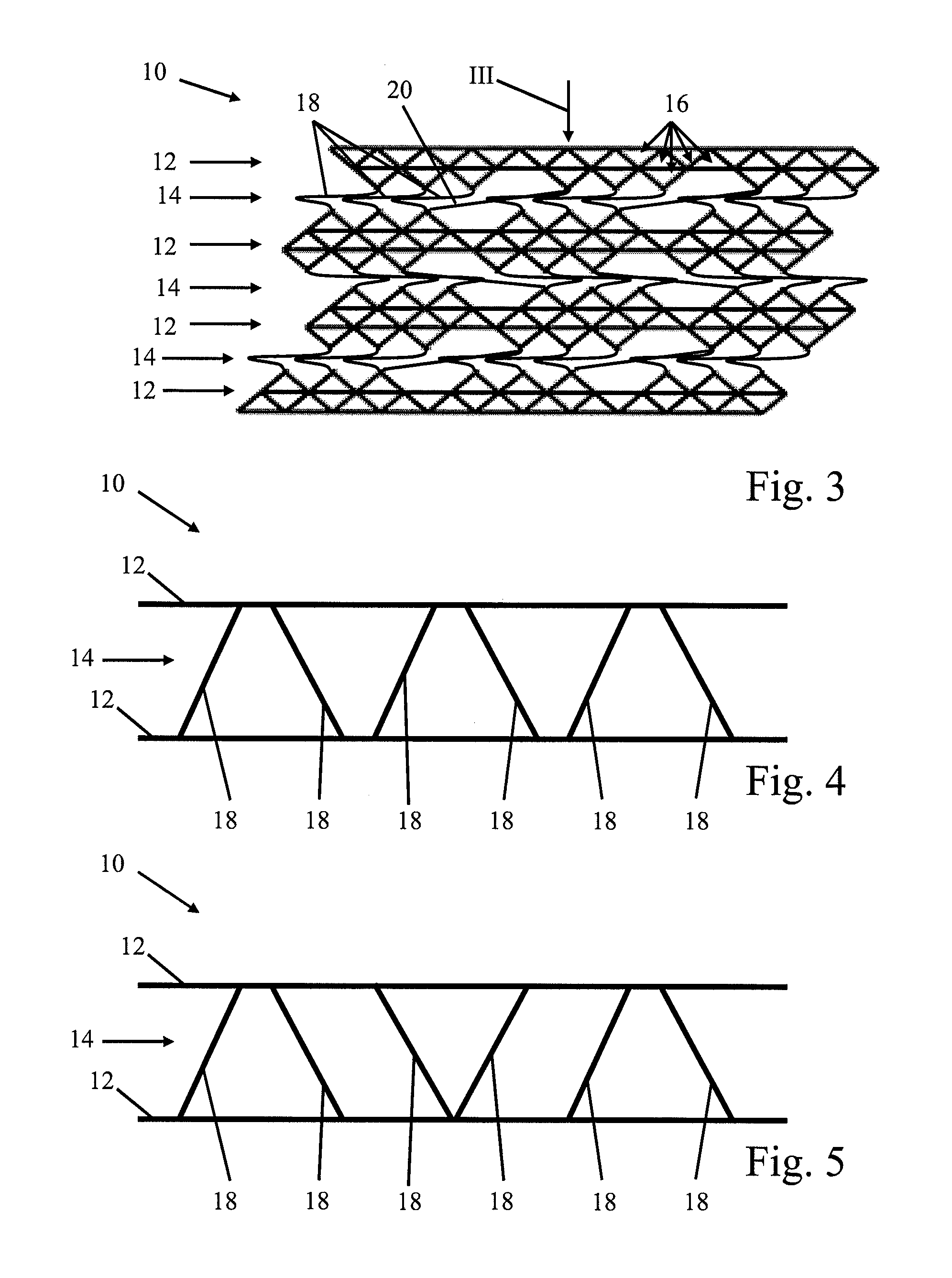
[0027]FIG. 1 shows a schematic side sectional view of a safety device 10 according to the invention for a bearing arrangement of a rotor of an aircraft engine. As a micro-structure, the safety device 10 comprises, by way of an example, an arrangement of four support structures 12 between each of which there is a buckling structure 14. The safety device 10 will be explained below in conjunction with FIGS. 2 and 3. FIG. 2 shows an enlarged depiction of the detail II shown in FIG. 1, whereas FIG. 3 shows a schematic side sectional view of the safety device 10 of FIG. 1 with a collapsed buckling structure 14.

[0028]The buckling structures 14 are configured in such a way that they collapse, thereby reducing the volume of the safety device 10, when a predetermined buckling load that acts on at least one of the support structures 12 and that is indicated in FIG. 3 by the arrow III is exceeded. In contrast, the support structures 12 are configured to be so stable that they mechanically separ...


PUM

PropertyMeasurementUnit
Angleaaaaaaaaaa
Angleaaaaaaaaaa
Structureaaaaaaaaaa

Abstract

A safety device (10) for a bearing arrangement of a rotor of a turbomachine, whereby the safety device (10) includes at least two support structures (12) between which at least one buckling structure (14) is arranged that is configured to collapse when a predetermined buckling load that acts on at least one of the support structures (12) is exceeded, thereby reducing the volume of the safety device (10). A method for the production of a safety device (10) for a bearing arrangement of a rotor of a turbomachine, as well as to a bearing arrangement of a rotor of a turbomachine having such a safety device (10).

Description

[0001]This claims the benefit of German Patent Application DE 10 2013 216 598.6, filed Aug. 21, 2013 and hereby incorporated by reference herein.[0002]The invention relates to a safety device for a bearing arrangement of a rotor of a turbomachine. Moreover, the invention relates to a method for the production of such a safety device as well as to a bearing arrangement of a rotor of a turbomachine having such a safety device.BACKGROUND[0003]In case of a blade failure in a turbine engine, for example, because of a bird strike or the like, high unbalances occur in the rotor which, in the worst-case scenario, can damage or even destroy the bearing arrangement of the rotor as well as other static structures, including the engine mount. In order to rule this out to the greatest extent possible, mechanical safety devices can be used that radially release the rotor when a limit force is exceeded, so that unbalance forces can no longer occur. A bearing arrangement with a safety device compri...

Claims


Application Information

Patent Timeline
IPC IPC(8): F01D21/04F16C17/24F01D25/16F16C19/52
CPCF01D21/045F16C19/522F05D2240/50F01D25/164F05D2240/20F16C17/24F05D2260/311
Inventor BOECK, ALEXANDER
Owner MTU AERO ENGINES GMBH
Why Eureka
Try Eureka