Device for providing a fluid having regulated output pressure

a technology of output pressure and fluid, applied in fluid pressure control, process and machine control, instruments, etc., can solve the problems of regulation hysteresis, inability to achieve sufficiently low energy consumption, and known devices are susceptible to fluctuating input pressure, etc., to achieve low energy consumption, simple design, and reduce output pressure

Active Publication Date: 2015-09-24
ASCO NUMATICS
View PDF22 Cites 9 Cited by
  • Summary
  • Abstract
  • Description
  • Claims
  • Application Information

AI Technical Summary

Benefits of technology

[0022]The mechanically simple design is advantageous in that slight mechanical friction is generated in the valve mechanics by the use of sliding bearings instead of O-ring seals.
[0023]An intermediate space having a fluidic connection to a ventilation opening is provided between the first and the second diaphragm. The advantage of this diaphragm is that overpressure or underpressure cannot develop between the two diaphragms, because the intermediate space is used for ventilation, which would adversely affect or at least delay the regulation.
[0024]The device preferably comprises a second valve unit for ventilating the outlet chamber, wherein the second valve unit acts between the coupling chamber and a ventilation opening. The second valve unit has a ventilation seat disposed between the second diaphragm and the control tube, which fluidically connects the intermediate chamber to the coupling chamber and interacts with a sealing surface on the control tube. A ventilation spring is provided that is disposed between the ventilation seat and a holding part for the control tube. This measure makes it possible, in a mechanically simple manner, to ventilate the device in the event that the pilot control pressure is reduced, in order to provide a lower output pressure.
[0025]The ventilation spring is used not only for reliable ventilation, but also for force displacement, thereby ensuring that output pressures in the underpressure range can also be regulated by means of pilot control pressures in the overpressure range.

Problems solved by technology

Highly accurate pressure controllers having an accuracy greater than 1% and, often, greater than 0.5%, are required for use in test devices and in special machines, which cannot be achieved by the known devices or cannot be achieved with sufficiently low energy consumption.
In addition, the regulation in the case of the known devices is associated with a notable frictional force and therefore has a regulation hysteresis.
Furthermore, the known devices are susceptible to fluctuating input pressure.
In addition, the switching noises of known devices are often perceived as being disadvantageous.
In the case of the known devices, it is furthermore disadvantageous that the output pressure often must remain noticeably lower than the input pressure, which is likewise disadvantageous in terms of energy.

Method used


Image

  • Device for providing a fluid having regulated output pressure
  • Device for providing a fluid having regulated output pressure
  • Device for providing a fluid having regulated output pressure

Examples


Embodiment Construction

[0038]The following is a detailed description of example embodiments of the invention depicted in the accompanying drawings. The example embodiments are presented in such detail as to clearly communicate the invention and are designed to make such embodiments obvious to a person of ordinary skill in the art. However, the amount of detail offered is not intended to limit the anticipated variations of embodiments; on the contrary, the intention is to cover all modifications, equivalents, and alternatives falling within the spirit and scope of the present invention, as defined by the appended claims.

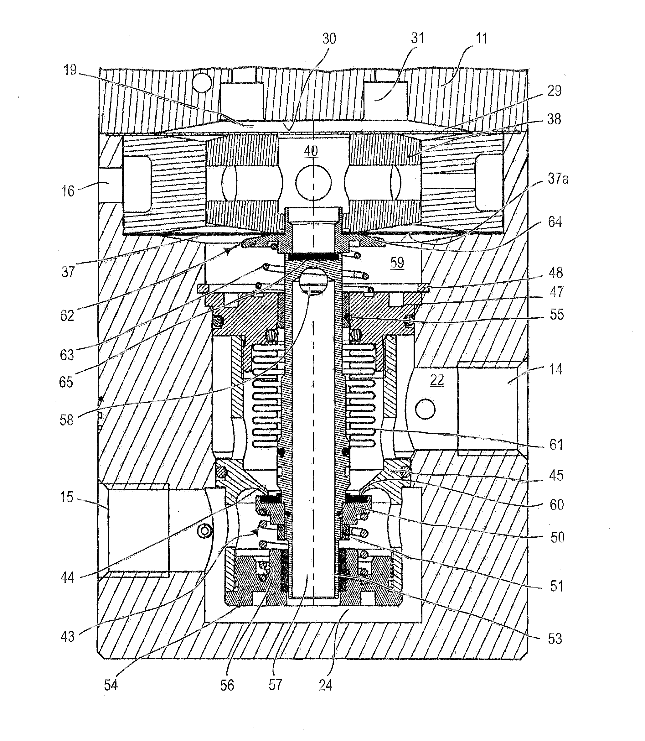
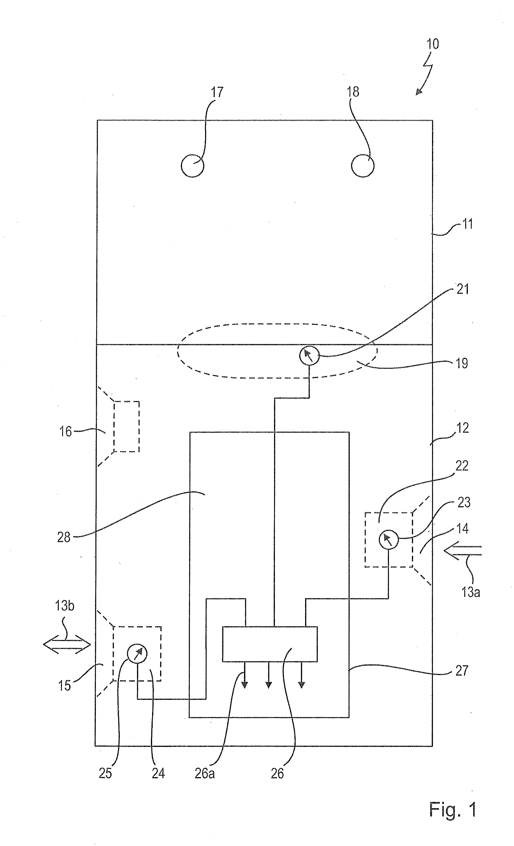
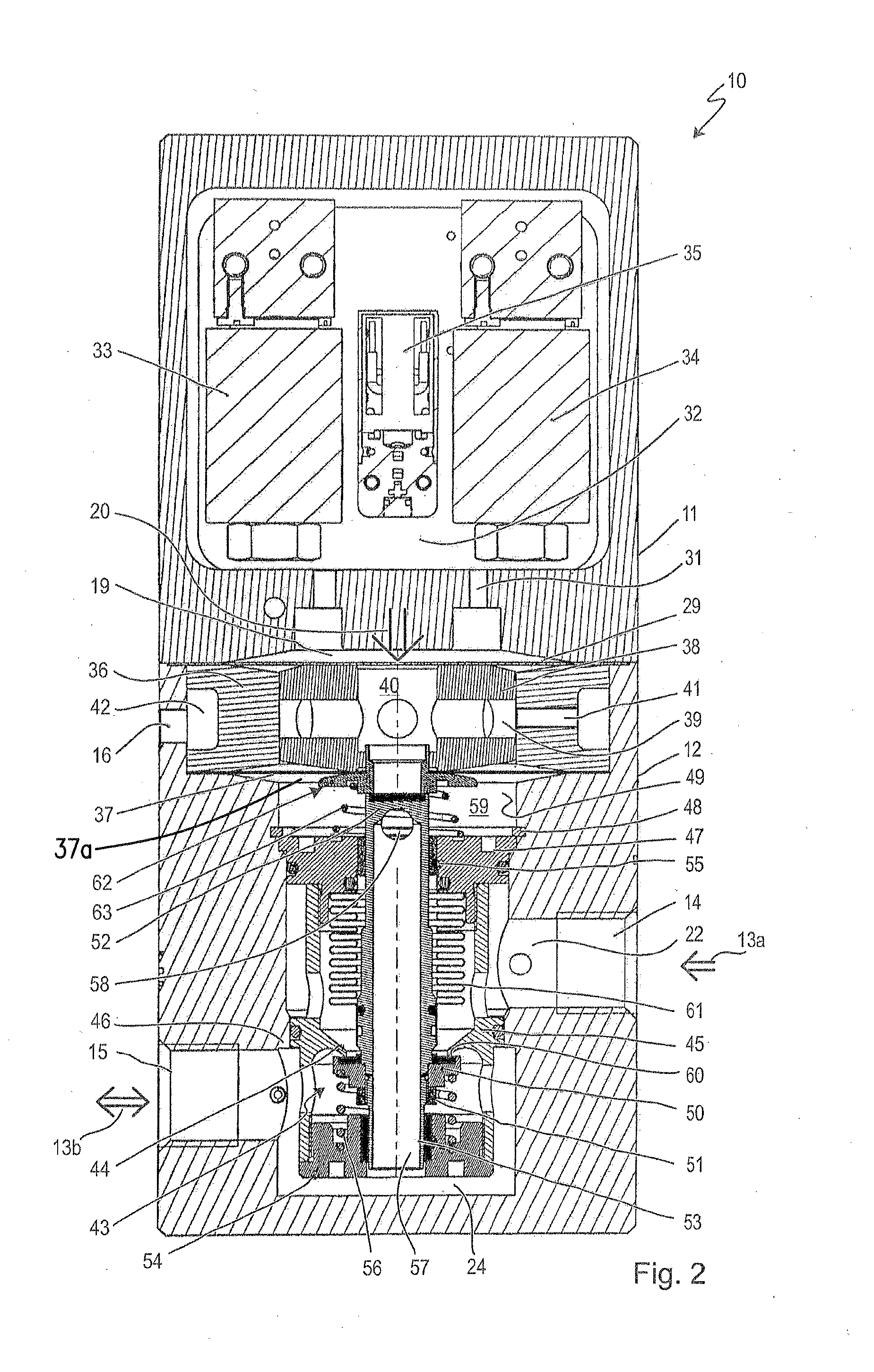
[0039]FIG. 1 presents a schematic front view of a device 10 for highly accurate and low-power pressure control. Device 10 comprises a pilot control valve 11 and a pressure control unit 12. The pilot control unit 11 and the pressure control unit 12 each have a housing, wherein the two housings are interconnected in a manner that is not shown.

[0040]The device 10 is used for the pressure regul...


PUM


Abstract

A device for providing an output fluid at a regulated output pressure includes a pressure control unit controlled via a pilot control pressure and a pilot control unit that provides the pilot control pressure. The pressure control unit includes an inlet chamber for an input fluid having an input pressure, an outlet chamber for the output fluid having the regulated output pressure and a first valve unit that acts between the inlet chamber and the outlet chamber. A first diaphragm of the pressure control unit is acted upon by the pilot control pressure. A second diaphragm, which is mechanically coupled to the first diaphragm is acted upon by the output fluid having the output pressure acts. At least the second diaphragm mechanically acts on the first valve unit.

Description

CROSS-REFERENCE TO A RELATED APPLICATION[0001]The invention described and claimed hereinbelow is also described in European Patent Application 14 161 000.6, filed on Mar. 21, 2014. The European Patent Application, the subject matters of which is incorporated herein by reference, provides the basis for a claim of priority of invention under 35 U.S.C. 119(a)-(d).BACKGROUND OF THE INVENTION[0002]The present invention relates to a device for providing a fluid having regulated output pressure. The device comprises a pressure control unit that is controlled via a pilot control pressure and comprises an inlet chamber for the fluid having an input pressure, an outlet chamber for the fluid having the regulated output pressure and a first valve unit that acts between the inlet chamber and the outlet chamber and comprises a pilot control unit that provides the pilot control pressure.[0003]Highly accurate pressure controllers having an accuracy greater than 1% and, often, greater than 0.5%, are...

Claims


Application Information

Patent Timeline
Patent Type & Authority Applications(United States)
IPC IPC(8): G05D7/06
CPCG05D7/0635G05D16/0672G05D16/2053G05D16/2095Y10T137/7759Y10T137/86598Y10T137/261Y10T137/86702
Inventor VOGT, MARTINSTEINLE, HARALDAMS, FELIX
Owner ASCO NUMATICS
Why Eureka
Try Eureka