Method for producing liquid discharge apparatus, liquid discharge apparatus, and method for forming liquid repellent layer
Active Publication Date: 2015-10-01
BROTHER KOGYO KK
View PDF1 Cites 0 Cited by
Summary
Abstract
Description
Claims
Application Information
AI Technical Summary
This helps you quickly interpret patents by identifying the three key elements:
Problems solved by technology
Method used
Benefits of technology
Benefits of technology
[0007]In the above recording head, the second insulating film is provided to prevent the moisture from arriving at the upper electrode films, the piezoelectric films, the lower electrode film, and the like. However, even the second insulating film exhibiting low moisture permeability has a possibilit
Problems solved by technology
Thus, in the above cases, desired discharge characteristics of ink, which is discharged from each nozzle at the time of driving the piezoelectric actuator, can not be obtained me
Method used
Image
Click on the blue label to locate the original text in one second.
Reading with bidirectional positioning of images and text.
Examples
Example
First Modified Embodiment
[0127]In the above embodiment, the surface protective layer 29 is disposed on the lower side of the liquid repellent layer 30. The present teaching, however, is not limited to this configuration. As depicted in FIG. 13, the surface protective layer 29 is not provided on the lower side of the liquid repellent layer 30 in a first modified embodiment. In this case also, the contact angle of the upper surface of the liquid repellent layer 30 is very high (140 degrees or more). Thus, the moisture adhering to the upper surface of the liquid repellent layer 30 can not penetrate the liquid repellent layer 30 and can not arrive at the individual electrodes 25, the piezoelectric layers 24, and the common electrode 23.
[0128]In the above embodiment, the liquid repellent layer 30 is made of the silane compound. The liquid repellent layer 30 may be made of organic material other than the silane compound. In a case that the liquid repellent layer 30 is formed by depositing...
Example
Second Modified Embodiment
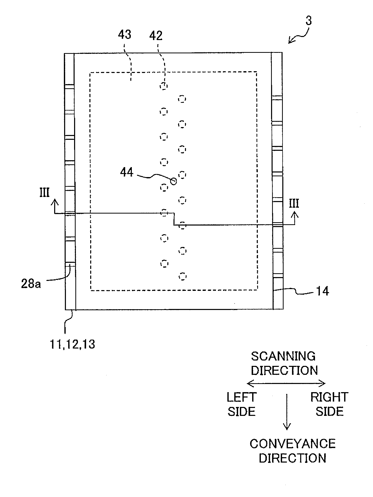
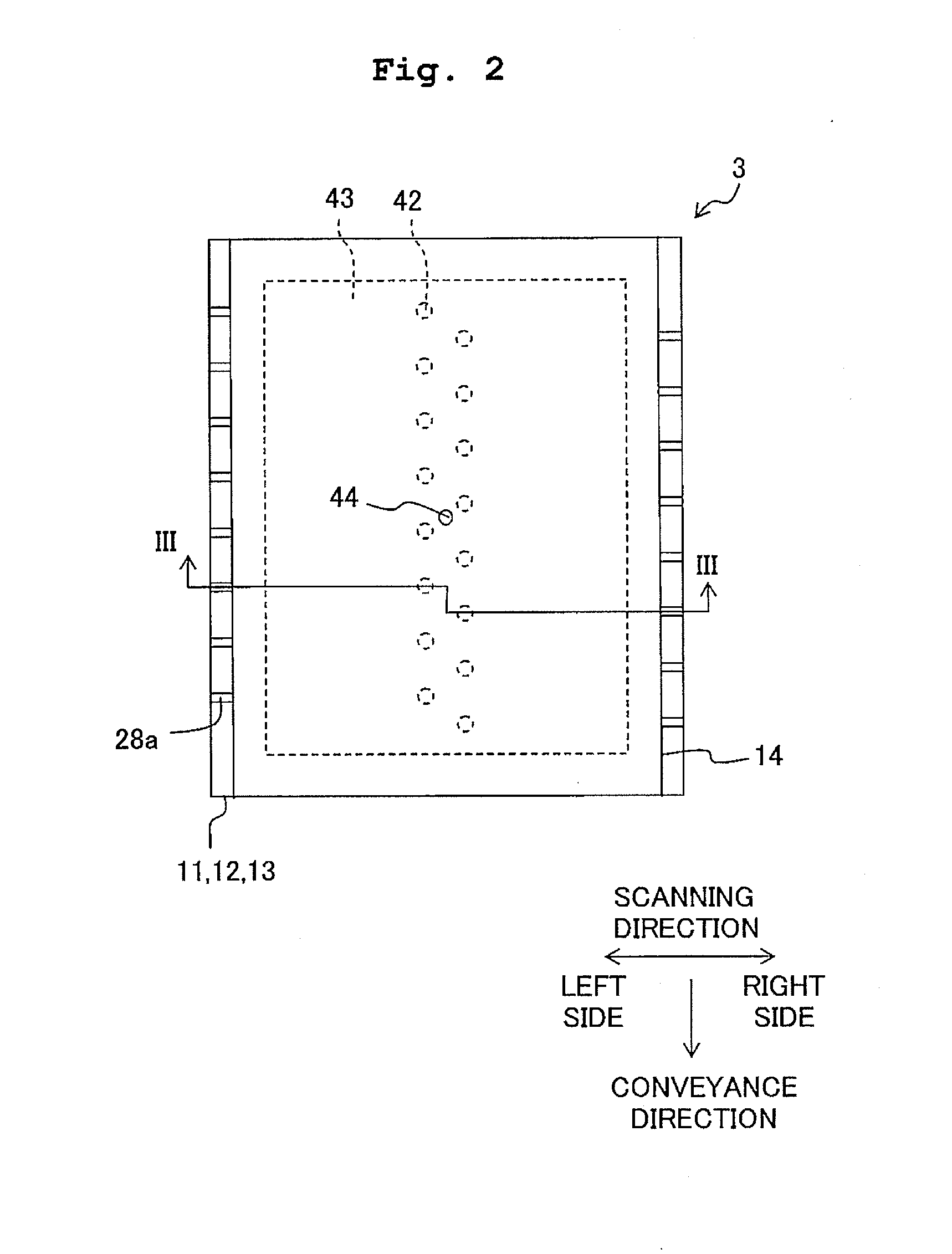
[0140]As depicted in FIG. 14, the protective member 14 (see FIG. 2) is not disposed on the upper surface of the piezoelectric actuator 13 in a second modified embodiment. Instead of the protective member 14, there is disposed a throttle channel forming member 60 in which the throttle channels 42 which are the same as those of the above embodiment are formed.
[0141]In this case, although the part of the piezoelectric actuator 13 overlapping with the piezoelectric layer 24 is exposed, the liquid repellent layer 30 can prevent moisture from reaching the common electrode 23, the piezoelectric layer 24, and the individual electrode 25.
[0142]In the second modified embodiment, there is disposed, above the throttle channel forming member 60, a member for supplying ink to the throttle channels such as a member for forming a space in which the ink is stored.
[0143]In the above embodiment, the explanation has been made about the case in which the ink-jet head 3 is obtai...
PUM
Abstract
There is provided a method for producing a liquid discharge apparatus including a piezoelectric actuator configured to apply pressure to liquid in pressure chambers formed in a channel forming substrate. The producing method includes: forming a stacked body of an ink separation layer, piezoelectric layers, a first electrode, and second electrodes on a base member having a part to be the channel formation substrate; forming a liquid repellent layer which covers the piezoelectric layers and the second electrodes from a side opposite to the ink separation layer; and forming the pressure chambers on the base member. The liquid repellent layer is formed to have residual stress generated in the liquid repellent layer in a state that the pressure chambers are formed, the residual stress having intensity which is smaller than intensity to bend parts of the piezoelectric actuator overlapping with the pressure chambers toward the pressure chambers by 200 nm.
Description
CROSS REFERENCE TO RELATED APPLICATION[0001]The present application claims priority from Japanese Patent Application No. 2014-072445, filed on Mar. 31, 2014, the disclosure of which is incorporated herein by reference in its entirety.BACKGROUND[0002]1. Field of the Invention[0003]The present teaching relates to a method for producing a liquid discharge apparatus configured to discharge liquid from nozzles, the liquid discharge apparatus configured to discharge the liquid from the nozzles, and a method for forming a liquid repellent layer by which the liquid repellent layer is formed in the liquid discharge apparatus.[0004]2. Description of the Related Art[0005]As a liquid discharge apparatus which discharges liquid from nozzles, there is conventionally known an ink-jet recording head which discharges ink from nozzles. In this recording head, a first insulating film is formed on the upper surface of an elastic film which is disposed to cover pressure chambers and a lower electrode fi...
Claims
Application Information
Patent Timeline
Application Date:The date an application was filed.
Publication Date:The date a patent or application was officially published.
First Publication Date:The earliest publication date of a patent with the same application number.
Issue Date:Publication date of the patent grant document.
PCT Entry Date:The Entry date of PCT National Phase.
Estimated Expiry Date:The statutory expiry date of a patent right according to the Patent Law, and it is the longest term of protection that the patent right can achieve without the termination of the patent right due to other reasons(Term extension factor has been taken into account ).
Invalid Date:Actual expiry date is based on effective date or publication date of legal transaction data of invalid patent.
