Electrostatic actuator, droplet discharging head, droplet discharging apparatus, electrostatic device, and method of manufacturing these

a technology of electrostatic actuators and actuators, which is applied in the field of electrostatic actuators, droplet discharging heads, droplet discharging apparatuses, and methods of manufacturing these. it can solve the problems of inability to control the capillary action, difficulty in miniaturizing the ink jet head, and different sealing conditions

Inactive Publication Date: 2006-06-29
SEIKO EPSON CORP
View PDF1 Cites 18 Cited by
  • Summary
  • Abstract
  • Description
  • Claims
  • Application Information

AI Technical Summary

Benefits of technology

[0017] Further, when the oxide film is made of an aluminum oxide film, the sealing material can be decreased in thickness because oxide aluminum is low in moisture permeation, which provides, however, a problem of difficult manufacturing of the ink jet head, etc. due to a long time necessary for film-formation, easy reaction to an alkaline solution.
[0074] According to the invention, the sealing material is encapsulated through the though-slot, and then there is used an electrostatic actuator having a reliable sealing portion formed therein. Therefore, it is possible to manufacture an electrostatic device having a long life.

Problems solved by technology

; however, when the sealing material is made of an epoxy resin material, the epoxy resin material unfavorably enters deep into the gap due to capillary action, thereby it is necessary to enlarge a margin to be sealed so as to prevent the sealing material from penetrating into the electrostatic actuator, which provides a problem of making it difficult to miniaturize the ink jet head.
Further, it is generally impossible to control the capillary action, which poses a problem that sealing conditions are different between gaps.
Also, in the conventional ink jet heads and the methods of manufacturing the same (for example, refer to Patent Document 1), the sealing is carried out by only one kind of the oxide film; however, when the oxide film is made of an oxide silicon film, for example, the sealing material needs to be increased in thickness because the silicon oxide film is high in moisture permeation, which provides a problem of making it difficult to miniaturize the ink jet head.
Further, when the oxide film is made of an aluminum oxide film, the sealing material can be decreased in thickness because oxide aluminum is low in moisture permeation, which provides, however, a problem of difficult manufacturing of the ink jet head, etc. due to a long time necessary for film-formation, easy reaction to an alkaline solution.
However, since it is in liquid form, the silicon-containing polyimide family sealing material unfavorably enters deep into the gap due to capillarity action, as is the case with the epoxy resin material, which provides a problem of making difficult it to miniaturize the ink jet head.
Further, in the manufacturing process, when the silicon-containing polyimide family sealing material is unfavorably adhered to a portion which originally does not require sealing, such as a portion connected to another substrate, or a portion as a terminal of a taken out electrode, the material prevents contact with the another substrate or electrical connection with electric power supplying means, which necessitates a removing process.
Moreover, forming the sealing layer of TEOS (tetraethyl orthosilicate) by a plasma CVD method prevents the sealing material from entering deep into the gap, thereby reducing a margin to be sealed, which results in two-dimensional miniaturization of the electrostatic actuator.
Further, forming the sealing layer of TEOS by a plasma CVD method reduces a margin to be sealed, which results in two-dimensional miniaturization of the electrostatic actuator.
Therefore, it is possible to reduce a margin to be sealed, which results in two-dimensional miniaturization of the droplet discharging head.

Method used


Image

  • Electrostatic actuator, droplet discharging head, droplet discharging apparatus, electrostatic device, and method of manufacturing these
  • Electrostatic actuator, droplet discharging head, droplet discharging apparatus, electrostatic device, and method of manufacturing these
  • Electrostatic actuator, droplet discharging head, droplet discharging apparatus, electrostatic device, and method of manufacturing these

Examples


first embodiment

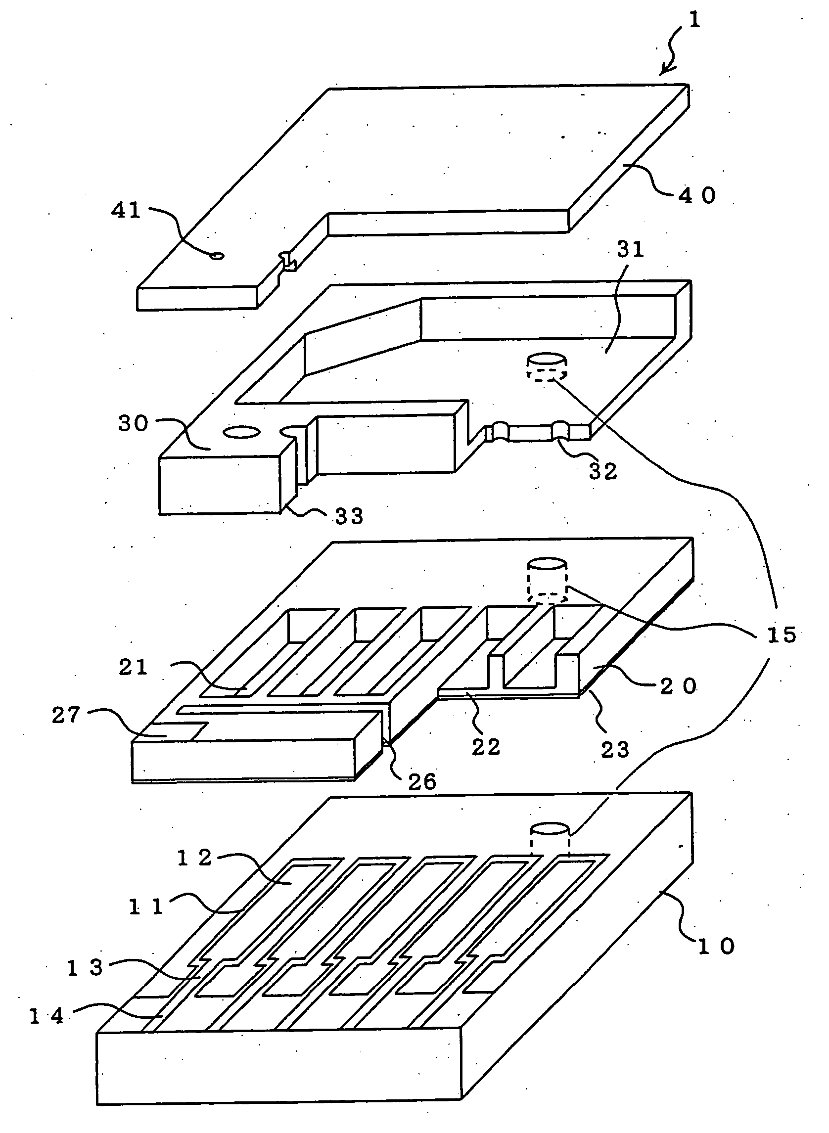
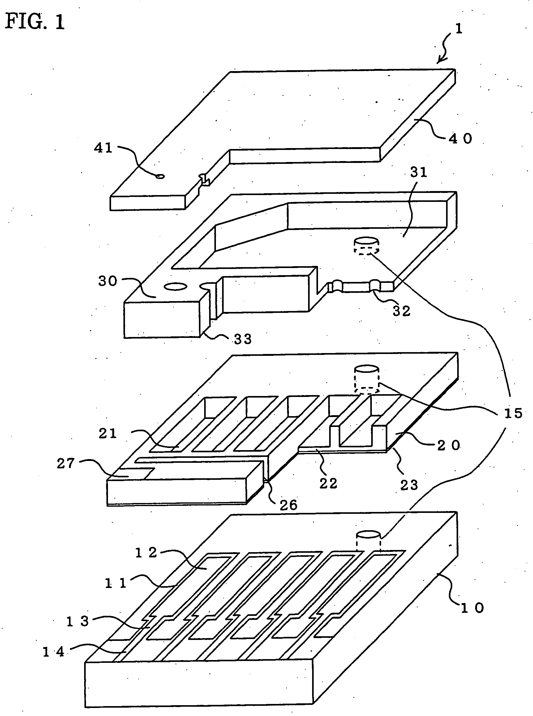
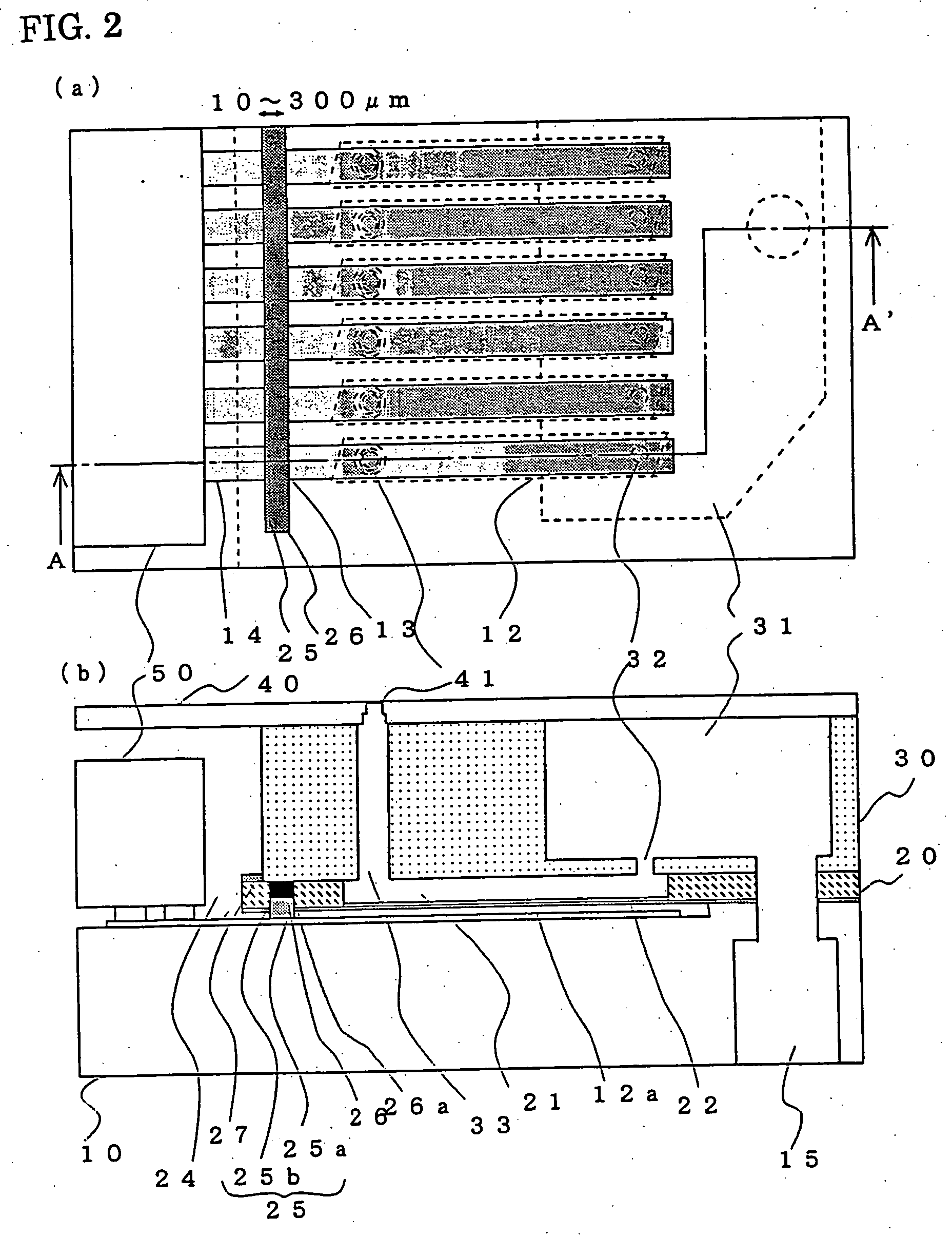
[0107]FIG. 1 is an exploded view of a droplet discharging head according to a first embodiment of the invention. FIG. 1 shows a part of the droplet discharging head. In addition, FIG. 2 is a top plan view and a vertical sectional view of the droplet discharging head, respectively. In this embodiment, there is illustrated a face-eject type droplet discharging head as a representative of devices which use an electrostatic actuator driven in an electrostatic manner. (Moreover, the following drawings including FIG. 1 may not provide actual dimensions of respective constitutional members in order to facilitate visualization of the illustrated constitutional members. Each of these drawings shows the constitutional elements while being kept upright.)

[0108] As shown in FIG. 1, a droplet discharging head according to this embodiment is constructed by four substrates of an electrode substrate 10, a cavity substrate 20, a reservoir substrate 30, and a nozzle substrate 40, which are laminated ...

second embodiment

[0132]FIG. 6 is a view showing a relationship between the through-slot 26 disposed in the cavity substrate 20 and the lead portion 13 disposed on the electrode substrate 10, according to a second embodiment of the invention. The above-mentioned first embodiment is illustrated assuming that the sealing material 25 is not adhered to a bonded surface between the cavity substrate 20 and the reservoir substrate 30. However, in the case where the attached silicon mask is separated from the cavity substrate 20 by a gap without close contact, or the alignment of the silicon mask is off, for example, it cannot be said that the sealing material 25 is not adhered to the bonded surface. Even if this happens, in this embodiment, a sealing material clearance groove 34 being preliminarily formed on the reservoir substrate 30 prevents the sealing material 25 from contacting the reservoir substrate 30, which prevents the poor bonding.

[0133] On this occasion, the sealing material clearance groove 34...

third embodiment

[0143] In the above-mentioned embodiment, the TEOS layer 25a and the moisture permeation preventing layer 25b are employed as the sealing material 25. Oxide silicon is the best material because it is superior in the resistance to liquid or gas which is used in the subsequent processes, but is not limited thereto. Further, the moisture permeation preventing layer 25b may include, for example, not only Al2O3 (aluminum oxide (alumina)), but also silicon nitride (SiN) and silicon oxynitride (SiON). Also, it may include substances, such as Ta2O5 (tantalum pentoxide), DLC (diamond like carbon), polyparaxylylene, PDMS (polydimethylsilxane: a kind of silicone rubber), an inorganic or organic compound including epoxy resin, etc., which are relatively lower in molecular mass and can be deposited by means of a vapor deposition method, a sputtering method, etc., and further are impermeable to moisture. Generally, the inorganic compound material is superior in a gas barrier property, a vapor bar...


PUM


Abstract

To provide an electrostatic actuator, etc. which is capable of miniaturizing the size, and preventing moisture, etc. from entering a gap in an effective manner. An electrostatic actuator includes an electrode substrate 10 having individual electrodes 12 as fixed electrodes, and a cavity substrate 20 having diaphragms 22 as movable electrodes which are disposed so as to be opposed to the fixed electrodes 12 with a predetermined distance, and operated due to an electrostatic force occurring between the cavity substrate 20 and the individual electrodes 12. Sealing portions 26a are formed on one of the electrode substrate 10 and the cavity substrate 20, each of the sealing portions 26a has a plurality of sealing layers (a TEOS layer 25a, a moisture permeation preventing layer 25b) laminated one another, and each of the sealing layers is made of a sealing material 25 for isolating a space formed between the individual electrode 12 and the diaphragm 22.

Description

[0001] The entire disclosure of Japanese Patent Application No. 2004-375687, filed Dec. 27, 2004, Japanese Patent Application No. 2005-200109, filed Jul. 8, 2005, Japanese Patent Application No. 2005-303453, filed Oct. 18, 2005, are expressly incorporated by reference herein. TECHNICAL FIELD [0002] The present invention relates to an electrostatic device, such as an electrostatic actuator, a droplet discharging head, etc. as a micromachined element in which a movable portion is displaced due to an applied force, etc., and hence is operated, etc., an apparatus using the device, and a method of manufacturing the same. More particularly, the present invention relates to sealing which is carried out in the micromachined element. BACKGROUND ART [0003] Recently, micro electro mechanical systems (MEMS), such as machining silicon, etc. to form a micro element, etc have made enormous progress. Examples of the micromachined element formed by micro electro mechanical systems (MEMS) include an ...

Claims


Application Information

Patent Timeline
Patent Type & Authority Applications(United States)
IPC IPC(8): B41J2/06
CPCB41J2/14314B41J2/16B41J2/1623B41J2/1629B41J2/1632B41J2/1635B41J2/1642B41J2/1646B41J2002/14411B41J2/045
Inventor MATSUSHITA, TOMONORIMATSUNO, YASUSHIFUJII, MASAHIRO
Owner SEIKO EPSON CORP
Why Eureka
Try Eureka