Supercharge Your Innovation With Domain-Expert AI Agents!

Cylindrical object locking device and method

Active Publication Date: 2015-10-01
ERICO INT
View PDF10 Cites 0 Cited by
  • Summary
  • Abstract
  • Description
  • Claims
  • Application Information

AI Technical Summary

Benefits of technology

The patent is about a device that securely locks a rod in place. It includes a lock nut that is screwed into the back plate and engages the plungers to prevent them from disengaging. The lock nut has a part that prevents it from being completely dislodged from the back plate. This device ensures that the rod stays secure and avoids any chance of accidental disengagement.

Problems solved by technology

However, prior items in the SPEED LINK product family have not included any quick threaded rod locking devices.
When installers install the pre-fabricated sub-assemblies on ceilings, structures, and sub-structures in the field, the installers cannot assemble them together without rotating threaded rod unless they disassemble the pre-fabricated sub-assemblies, because the threaded rod is a part of the pre-fabricated sub-assemblies.

Method used


Image

  • Cylindrical object locking device and method
  • Cylindrical object locking device and method
  • Cylindrical object locking device and method

Examples


Embodiment Construction

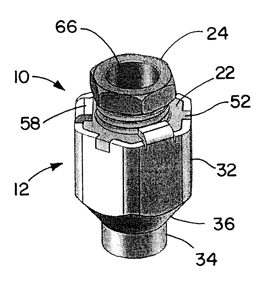
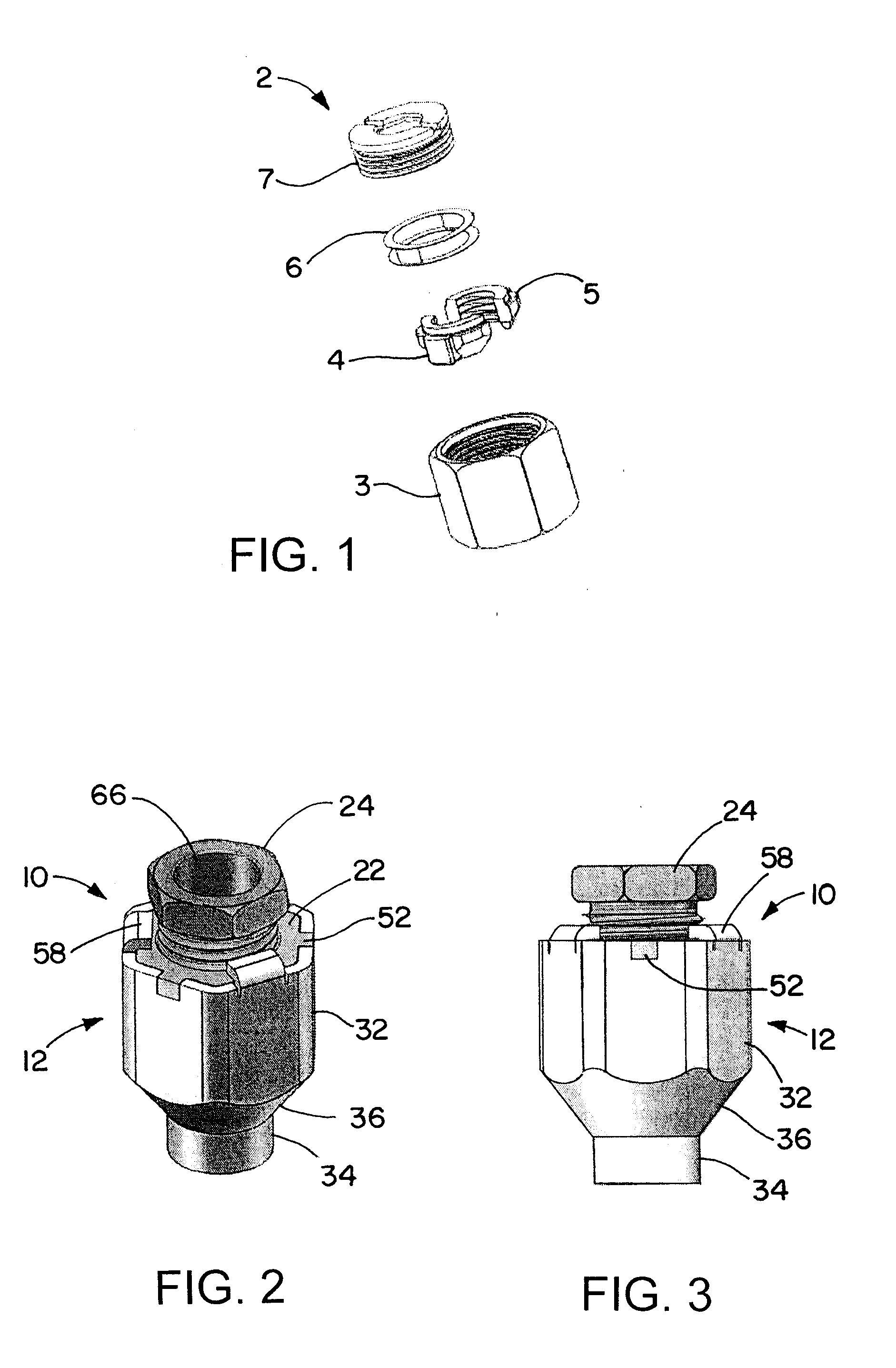
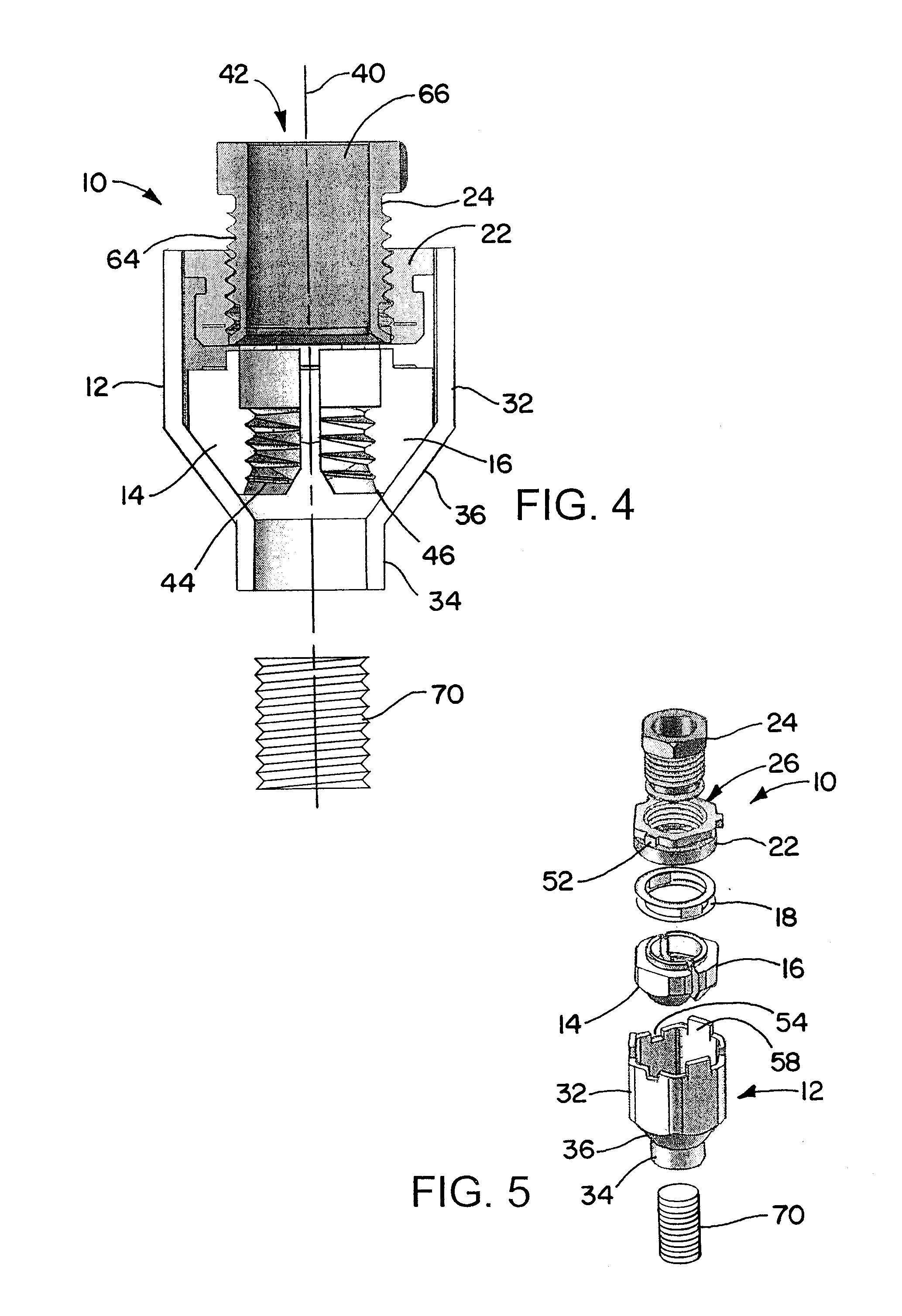
[0062]A locking or securement device, for securing a threaded rod or other cylindrical object, includes a pair of plunger pieces (plungers) within a housing. The plunger pieces act as quick lock mechanism to engage and secure a threaded rod that passes into a hole that runs through the housing. The plunger pieces have tapered outer surfaces and are spring-biased to position themselves toward so as to provide a radially inward force, for example to engage a threaded rod or device in the through hole in the housing. A spring within the housing presses the plunger pieces toward a portion of the housing where the outer surfaces engage other surfaces to push the plunger pieces (or plungers) inward, with the spring located between the plunger pieces and a back plate or cap that closes off part of a wide end of the tapered bore. The plunger pieces have internally threaded, toothed, or otherwise textured surfaces that engage threads on a threaded rod that is inserted into the bore, between ...


PUM


Abstract

A securement device includes a pair of plungers movable within a housing. The plungers act as quick lock mechanism to engage and secure a threaded rod (or other object) that passes into a hole that runs through the housing. The plungers are spring-biased to position themselves toward so as to provide a radially inward force, for example to engage a threaded rod or device in the through hole in the housing. A spring within the housing presses the plunger pieces toward a portion of the housing where the outer surfaces engage other surfaces to push the plungers inward. The device includes a disengagement feature or mechanism that is used to push the plunger pieces out of engagement with the threaded rod. The disengagement feature may include a disengagement tool, and may include wings, such as on the plungers or on carriers for the plungers, that protrude out of the housing.

Description

[0001]This application claims priority of U.S. Provisional Application 61 / 973,416, filed Apr. 1, 2014, the entire disclosure of which is incorporated by reference herein.BACKGROUND OF THE INVENTION[0002]1. Technical Field of the Invention[0003]The invention is in the field devices for locking onto threaded rods or other cylindrical objects.[0004]2. Description of the Related Art[0005]ERICO International Corporation sells the CADDY® SPEED LINK product family as a quick cable locking system that provides a means to suspend static loads from ceilings, structures, and sub-structures. However, prior items in the SPEED LINK product family have not included any quick threaded rod locking devices.[0006]In recent years, installers in the field are increasingly using pre-fabricated, sub-assembled parts in order to maximize their installation labor savings. When installers install the pre-fabricated sub-assemblies on ceilings, structures, and sub-structures in the field, the installers cannot ...

Claims


Application Information

Patent Timeline
IPC IPC(8): F16B39/24
CPCF16B39/24F16B37/0857F16B37/0821
Inventor OH, MICHAEL H.-SKORTE, PETER B.LAUGHLIN, RAYMOND S.OLLE, RAYMOND M.LYONS, DAVIDJONES, RONALD A.AMBROGIO, NICHOLAS J.
Owner ERICO INT
Features
  • R&D
  • Intellectual Property
  • Life Sciences
  • Materials
  • Tech Scout
  • Unparalleled Data Quality
  • Higher Quality Content
  • 60% Fewer Hallucinations
Learn More