Magazine floor plate

a floor plate and magazine technology, applied in the field of magazines, can solve the problems of requiring a tool in order to remove the floor plate, the risk of forcible ejection of the spring plate, and the limitation of acp magazines to seven rounds, so as to improve the appreciation of the contribution to the art

Active Publication Date: 2015-10-01
C PROD DEFENSE
View PDF12 Cites 23 Cited by
  • Summary
  • Abstract
  • Description
  • Claims
  • Application Information

AI Technical Summary

Benefits of technology

[0011]There has thus been outlined, rather broadly, the more important features of the invention in order that the detailed descrip

Problems solved by technology

This process has the disadvantage of requiring a tool in order to remove the floor plate.
There is also a risk of forcible ejection of the spring plate by the compressed magazine spring 114 once the floor plate is disengaged from the magazine.
Conventional 45 ACP magazines are also limited to seven rounds because the spring plate and follower occupy a portion of the interior volume of the magazine.
This is sometimes achieved by adding an extension to the lower end of the magazine, but this is oft

Method used


Image

  • Magazine floor plate
  • Magazine floor plate
  • Magazine floor plate

Examples


Embodiment Construction

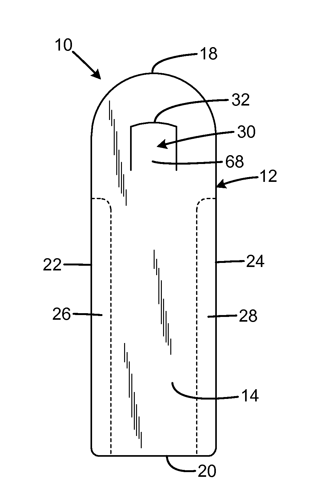
[0026]An embodiment of the magazine floor plate of the present invention is shown and generally designated by the reference numeral 10.

[0027]FIGS. 3A & 3B illustrate the improved magazine floor plate 10 of the present invention. More particularly, the magazine floor plate 10 is a substantially planar body 12 having a top 14, bottom 16, front 18, rear 20, left side 22, and right side 24. An upwardly protruding latch tab 30 is located near the radiused front of the floor plate. The latch tab is oriented so the front 32 is a sharp step relative to the top of the body, and the top 68 of the latch tab forms a gentle rearward-facing slope. The left side defines a left groove 26, and the right side defines a right groove 28. The left and right grooves begin rearward of the latch tab and extend to the rear of the body. In the current embodiment, the latch tab is lanced in the body (the lance tool cuts through the body, but does not remove the material to leave a through hole). The left and ...


PUM

PropertyMeasurementUnit
Widthaaaaaaaaaa

Abstract

Magazine floor plates have a tubular body defining an elongated passage and having a lower end and an upper end, a floor plate element connected to the lower end, a follower movable within the elongated passage, a spring within the passage having a first end contacting the floor plate element, and having an opposed second end contacting and biasing the follower toward the upper end of the body. Downward force exerted by the spring on the floor plate element retains the floor plate element in an installed position relative to the lower end of the body. The floor plate element may have a width narrower than the elongated passage. The floor plate element may be connected to the lower end of the body by rails on the lower end of the body. The floor plate element may have an upward protrusion.

Description

FIELD OF THE INVENTION[0001]The present invention relates to firearms, and more particularly to a magazine floor plate for a box magazine.BACKGROUND OF THE INVENTION[0002]A magazine is an ammunition storage and feeding device within, or attached to, a repeating firearm. The magazine functions by moving the cartridges stored in the magazine into a position where they may be chambered by the action of the firearm. Most magazines designed for use with a reciprocating bolt firearm utilize a set of feed lips which stops the vertical motion of the cartridges out of the magazine but allows one cartridge at a time to be pushed forward (stripped) out of the feed lips by the firearm's bolt into the chamber.[0003]Some form of spring and follower combination is almost always used to feed cartridges to the lips, which can be located either in the magazine (most removable box magazines) or built into the firearm (fixed box magazines). As the firearm cycles, cartridges are moved to the top of the ...

Claims


Application Information

Patent Timeline
IPC IPC(8): F41A9/65F41A11/00
CPCF41A11/00F41A9/65F41A9/71F41A9/70Y10T29/49824
Inventor SHREVE, BERNIE
Owner C PROD DEFENSE
Why Eureka
Try Eureka