Coil unit and wireless power transmission device
a power transmission device and coil technology, applied in the direction of transformers, electromagnetic wave systems, inductances, etc., can solve the problems of suppressing the decrease of power transmission efficiency, preventing the increase of magnetic body more effectively, and reducing the leakage of magnetic field
- Summary
- Abstract
- Description
- Claims
- Application Information
AI Technical Summary
Benefits of technology
Problems solved by technology
Method used
Image
Examples
first embodiment
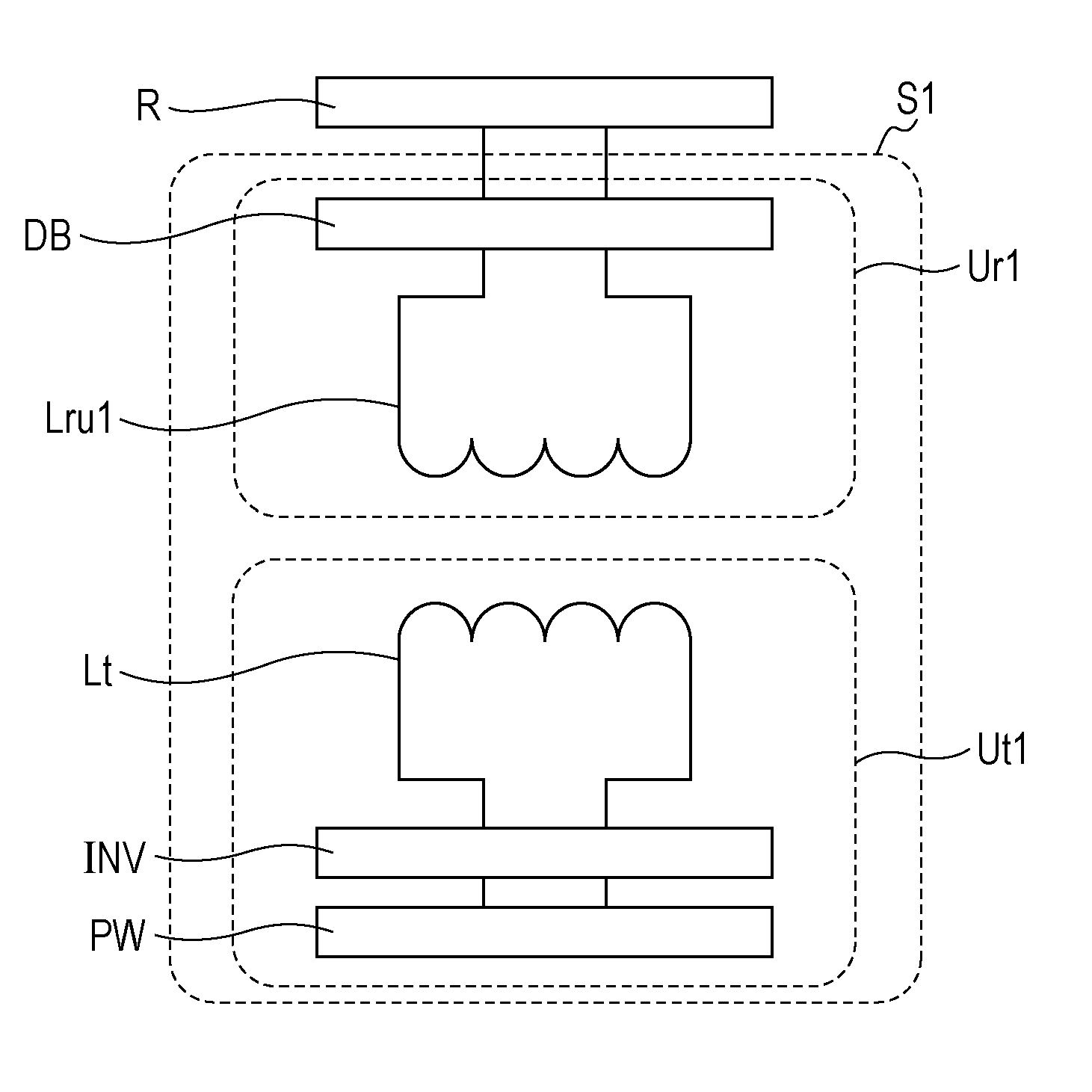
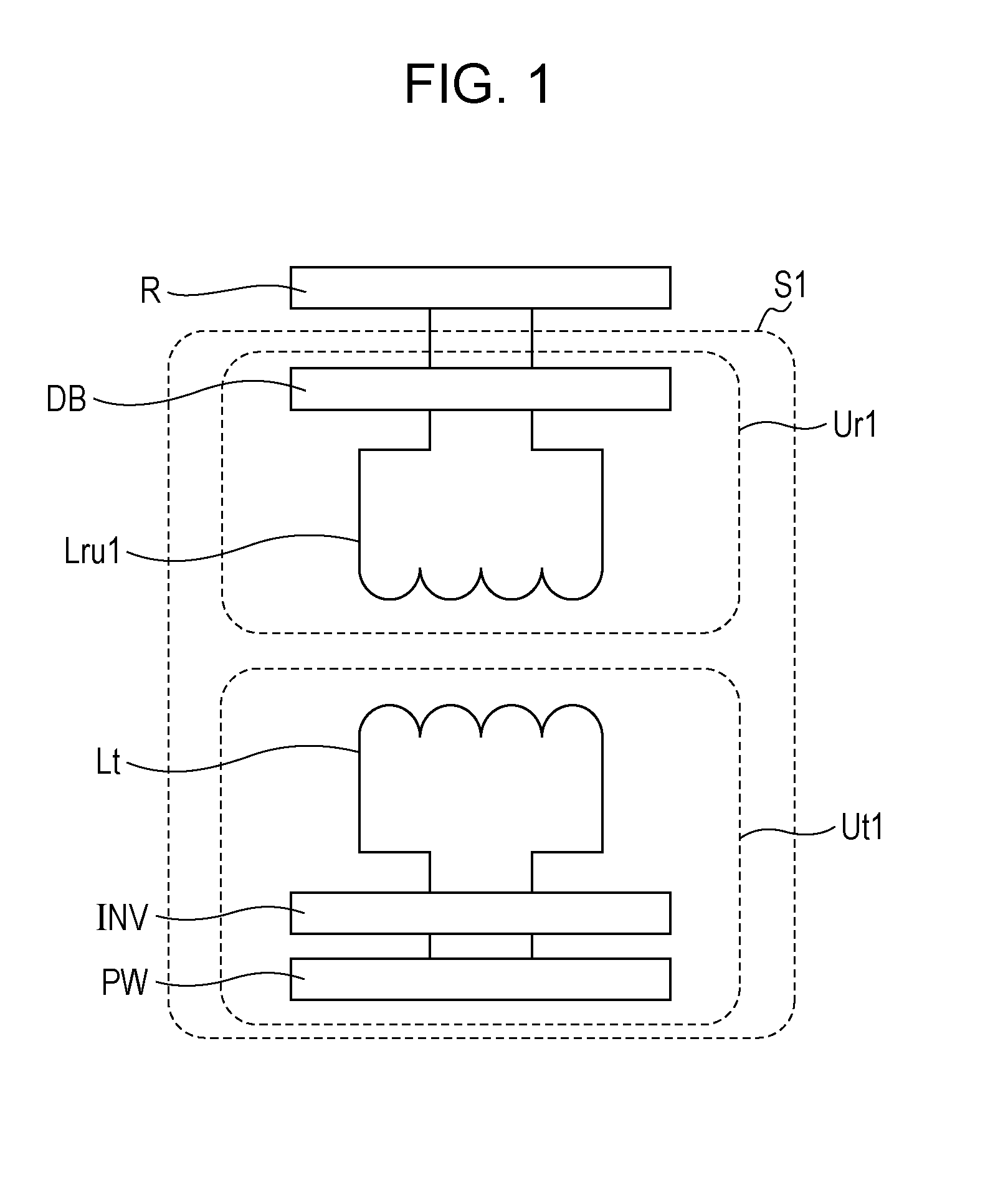
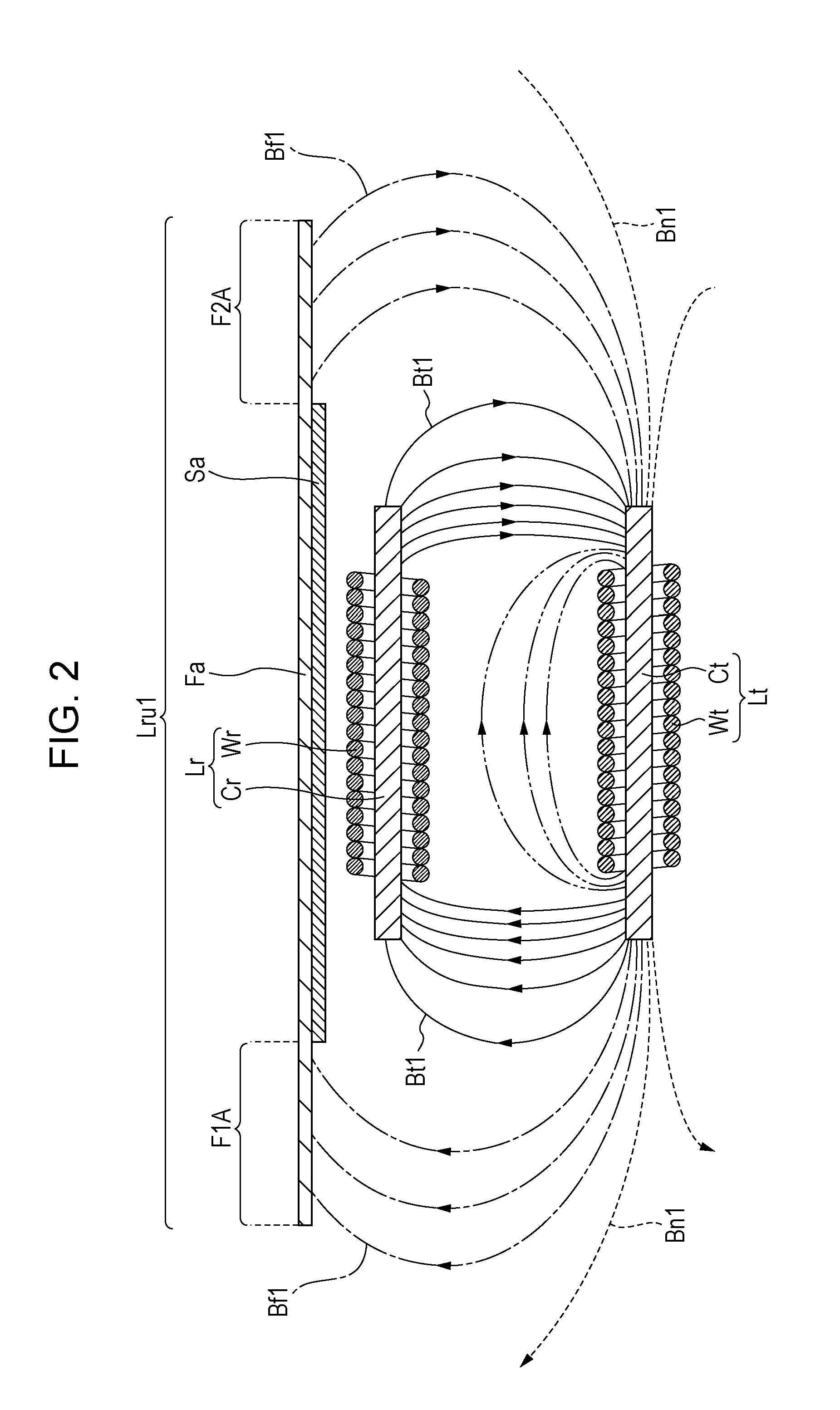
[0028]An entire configuration of a wireless power transmission device S1 according to a first embodiment of the present invention will be first described with reference to FIG. 1 and FIG. 2. In the present embodiment, an example in which a coil unit according to the present invention is applied to a power receiving coil unit of the wireless power transmission device is described. FIG. 1 is a system configuration diagram illustrating the wireless power transmission device according to the first embodiment of the present invention, and a load. FIG. 2 is a schematic cross-sectional diagram illustrating a transmission coil and a power receiving coil unit, according to the first embodiment of the present invention. FIG. 2 schematically illustrates magnetic fluxes which are generated by a transmission coil Lt. In FIG. 2, magnetic fluxes in the inside of magnetic cores Ct and Cr of a transmission coil Lt and a power receiving coil Lr, and a magnetic flux in the inside of magnetic body Fa a...
second embodiment
[0049]Next, the wireless power transmission device S1b according to a second embodiment of the present invention will be described with reference to FIG. 3. FIG. 3 is a diagram schematically illustrating a magnetic flux which is generated by first and second transmission coils, in a cross-sectional diagram illustrating a power receiving coil unit according to a second embodiment of the present invention, the first and second transmission coils, and a magnetic core of the first and second transmission coils. However, the figure schematically illustrates a magnetic flux which is generated by the first and second transmission coils Lta and Ltb, and does not illustrate magnetic fluxes in the inside of magnetic cores Ctb and Cr of the first and second transmission coils Lta and Ltb and the power receiving coil Lr, and the magnetic body Fa. In addition, in FIG. 3, as representations of the magnetic fluxes which are generated by the first and second transmission coils Lta and Ltb, a magnet...
third embodiment
[0062]Next, a wireless power transmission device S2 according to a third embodiment of the present invention will be described with reference to FIG. 4. In the present embodiment, an example in which a coil unit according to the present invention is applied to a transmission coil unit of a wireless power transmission device will be described. FIG. 4 is a diagram schematically illustrating magnetic fluxes which are generated by the transmission coil, in a cross-sectional diagram illustrating a transmission coil unit according to the third embodiment of the present invention and a power receiving coil. However, in the figure, magnetic fluxes in the magnetic cores Ct and Cr of the transmission coil Lt and a power receiving coil Lr, and a magnetic flux in the magnetic body Fb are not illustrated. In addition, in FIG. 4, as representations of the magnetic fluxes which are generated by transmission coil Lt, a magnetic flux Bt2 which is interlinked with the power receiving coil Lr, a magne...
PUM
 Abstract
Description
Claims
Application Information
 - R&D
- Intellectual Property
- Life Sciences
- Materials
- Tech Scout
- Unparalleled Data Quality
- Higher Quality Content
- 60% Fewer Hallucinations
Browse by: Latest US Patents, China's latest patents, Technical Efficacy Thesaurus, Application Domain, Technology Topic, Popular Technical Reports.
© 2025 PatSnap. All rights reserved.Legal|Privacy policy|Modern Slavery Act Transparency Statement|Sitemap|About US| Contact US: help@patsnap.com


