Measurement of Lay Length of Wire Rope

a technology of lay length and measurement method, applied in the direction of electric/magnetic measurement arrangement, magnetic field measurement using flux-gate principle, using electrical/magnetic means, etc., can solve the problems of wire ropes that are often of considerable length, carry considerable loads, and have to be prone to failur

Active Publication Date: 2015-10-08
HER MAJESTY THE QUEEN & RIGHT OF CANADA REPRESENTED BY THE MIN OF NATURAL RESOURCES
View PDF3 Cites 15 Cited by
  • Summary
  • Abstract
  • Description
  • Claims
  • Application Information

AI Technical Summary

Benefits of technology

[0011]The changes of magnetic flux may be sensed by various kinds of devices, for example Hall effect devices located where the magnetic flux circuit enters or leaves the region of the wire rope, flux gate sensors, or electrical induction coils positioned within the magnetic field surrounding the region of the wire rope. The electrical induction coils may be positioned at points where the magnetic flux circuit enters or leaves the region of the wire rope conducting the magnetic flux, or at any point along the region.
[0012]In another exemplary aspect, the invention provides apparatus for measuring lay length of a wire rope having a number of spirally wound external strands with grooves between the strands causing the wire rope to have a spirally grooved outer surface undulating in surface height from a central axis of the wire rope, and having lay length over which each of the strands completes a single circumferential spiral path around the wire rope. The apparatus includes a sensor device having a sensor body defining an elongated passageway enabling the wire rope to be advanced there-through in a direction of the central axis of the wire rope while permitting limited lateral movements of the wire rope. The sensor device has one or more generators of magnetic flux positioned to create a magnetic flux circuit having a part thereof passing through a region of the wire rope present in the passageway. Sensors are provided on the body capable of sensing changes of magnetic field strength or magnetic flux in the region of the rope caused by variations of proximity of the wire rope to the sensors, the sensors being located at two or more positions spaced circumferentially around the passageway. The sensors generate signals corresponding to the changes sensed at the two or more positions, and the signals each include components due to surface height and components due to lateral movements of the wire rope at the positions. Means (e.g. an electrical circuit) are provided for subtractively combining the signals from the sensors at the at least two positions to eliminate the components due to the lateral movements to produce a combined signal having an oscillating pattern caused by variations of surface height of the wire rope. The apparatus also has means (e.g. an electrical circuit) for associating oscillations in the oscillating pattern with physical distances along the wire rope, and a lay length calculator or display that calculates or displays a distance along the wire rope of a plurality of the oscillations corresponding in number to the number of spirally wound external strands of the wire rope.
[0013]In the apparatus, the sensors may be of various kinds, e.g. Hall effect devices, flux gate sensors, or electrical wire induction coils positioned around the passageway. The sensors may lie in a common plane transverse to a longitudinal axis of the passageway and may be separated from a central axis of the passageway by equal distances. In one embodiment, the device has twice as many sensors as external strands of the wire rope used with the apparatus, with a first half of the sensors all connected together and a second half of the sensors all connected together, and with the sensors of the first half alternating with the sensors of the second half around the passageway.

Problems solved by technology

For such applications, wire ropes often have to be of considerable length, e.g. 10,000 feet or more, and must carry considerable loads, including the weight of the ropes themselves in the sections between the conveyances and the mine hoists at the surface used for their deployment.
Local variations also occur in the rope at crossover points and can also occur due to localized faults as a result of a number of causes, e.g. corrosion, core deterioration, wire breakage, rope rotation (i.e. strand unlaying), or physical contacts.
In general, however, if the lay length of a rope or a section of a rope changes beyond defined limits, or if it changes locally, this may indicate potential failure of the rope, requiring a need for rope replacement.
Furthermore, direct measurement of the lay length of an entire rope is difficult and prone to error because of the lengths of such ropes.
On the other hand, measurement of lay length when the rope is in place in lifting apparatus, and especially when the rope is in use, is also difficult, especially because the rope may be covered in grease, dirt and / or provided with a protective cover or sheath made of plastics or other material, thereby obscuring the strands from visual inspection.
This is a problem for equipment that relies on the use of photographic imaging or other visual means, such as that disclosed in US published patent application No. 2009 / 0232383 A1 to Roland Verreet published on Sep. 17, 2009, or published International patent application WO 2011 / 112734 to Cornelison et al. published on Sep. 15, 2011.
However, this device does not measure the lay length of the braided wire, but rather makes an assumption of the lay length to detect a fault.

Method used


Image

  • Measurement of Lay Length of Wire Rope
  • Measurement of Lay Length of Wire Rope
  • Measurement of Lay Length of Wire Rope

Examples


Embodiment Construction

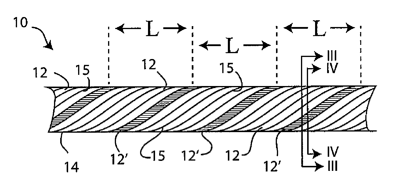
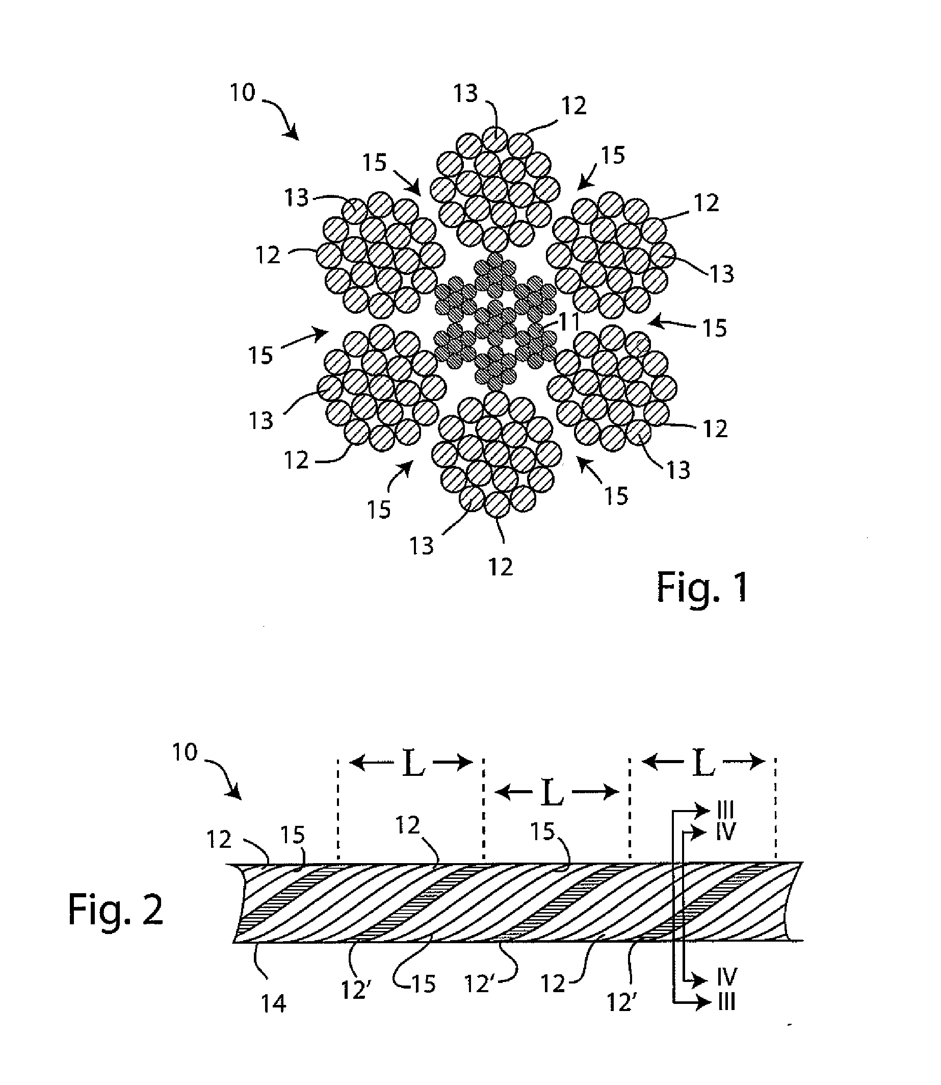
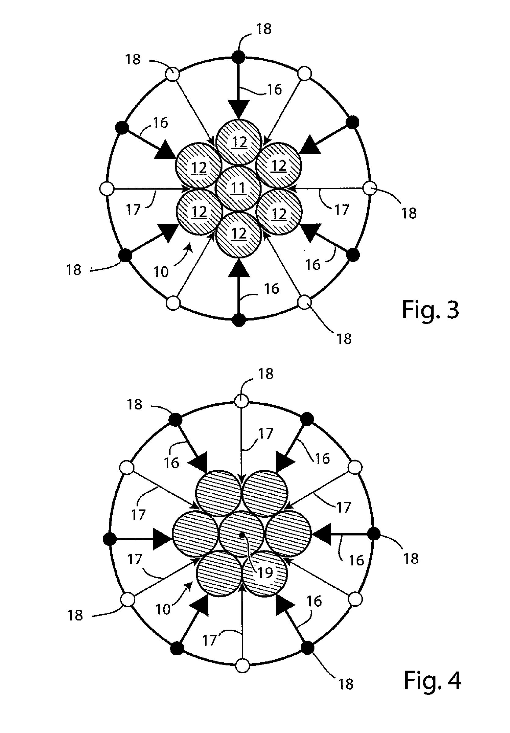
[0027]FIGS. 1 and 2 of the accompanying drawings show a cross-section of one form of wire rope 10 having a core strand 11 covered by six spirally wound outer strands 12 typically used for mining operations, although it should be kept in mind that wire ropes of other designs may alternatively be employed, e.g. those having more or fewer external strands, more or fewer core strands 11, and strands of non-circular cross-section. The core strand 11 and the external strands 12 are each made up of bundles of individual metal wires 13 twisted together. As best seen in FIG. 2, the outer surface 14 of the rope is formed by the external strands 12 separated by grooves 15 between the strands, thereby causing the rope to have a spirally grooved outer surface undulating in surface height from the central axis 19 (see FIG. 4) of the wire rope. Each of the external strands 12 twists around the rope in spiral loops separated from each other along the rope by the five other strands 12. In FIG. 2, on...


PUM

PropertyMeasurementUnit
lengthaaaaaaaaaa
lengthaaaaaaaaaa
surface heightaaaaaaaaaa

Abstract

The invention relates to a method and apparatus for measuring lay length of a wire rope having a number or external strands to form a rope having spiral grooves in the surface between the strands. A magnetic flux circuit is generated, part of which is formed within a region of the advancing wire rope. Variations of magnetic field around the region of the rope or variations of magnetic flux entering or leaving the rope are sensed by at least two sensors arranged around the rope. Signals from the sensors are subtractively combined to eliminate variations due to off-axis movements of the rope, and the combined signals reveal an oscillating pattern due to the undulating surface of the rope. Linking the oscillating pattern to distance along the rope reveals the lay length, which corresponds to a number of oscillations which is the same as the number of strands at the surface.

Description

TECHNICAL FIELD[0001]This invention relates to the measurement of lay length of wire ropes. More particularly, the invention relates to methods and apparatus for carrying out such measurements while the wire ropes are in use and under tension.BACKGROUND ART[0002]Wire ropes are used for many purposes such as ropeways, cable cars, ski lifts, chairlifts and elevators, but are of particular importance in the mining industry where they are used for raising and lowering conveyances holding miners, equipment and ore between the mining galleries and the surface. For such applications, wire ropes often have to be of considerable length, e.g. 10,000 feet or more, and must carry considerable loads, including the weight of the ropes themselves in the sections between the conveyances and the mine hoists at the surface used for their deployment.[0003]To ensure operational safety and long operational life of the equipment, the physical condition of such ropes must be monitored frequently and the r...

Claims


Application Information

Patent Timeline
Patent Type & Authority Applications(United States)
IPC IPC(8): G01N27/82D07B1/14G01B7/04
CPCG01N27/82D07B1/145G01B7/046G01R33/04G01R33/07D07B2301/555D07B2201/2026D07B2301/251D07B2301/45D07B2501/2007G01N27/90G01N27/83
Inventor OUELLETTE, SYLVAIN
Owner HER MAJESTY THE QUEEN & RIGHT OF CANADA REPRESENTED BY THE MIN OF NATURAL RESOURCES
Why Eureka
Try Eureka