System and method for detecting the depth of an antenna in the card body of a smart card

a smart card and antenna technology, applied in the field of smart cards, can solve the problems of compromising the overall operability of the smart card, unable to mill a cavity into the card body to the proper depth, and the contact terminal of the antenna would not be adequately exposed for direct connection, etc., to achieve the effect of simple, efficient and precise manner

Inactive Publication Date: 2015-10-08
AMERICAN BANKNOTE
View PDF2 Cites 9 Cited by
  • Summary
  • Abstract
  • Description
  • Claims
  • Application Information

AI Technical Summary

Benefits of technology

The present invention is about a system and method that can compensate for variations in the thickness of a card. It can accurately detect the depth of the antenna in the card without being affected by the surrounding conditions or interference. This makes it easier to manufacture and use the cards.

Problems solved by technology

If the cavity is not milled to the requisite depth, the antenna contact terminals would not be adequately exposed for direct connection.
By contrast, if the cavity is milled beyond the requisite depth, the antenna contact terminals may become damaged and therefore compromise the overall operability of the smart card.
However, it has been found that milling a cavity into the card body to the proper depth is often rendered challenging due to natural variances in card thickness resulting from, inter alia, material thickness tolerances of individual layers in the card body as well as process tolerances during lamination of the card body.
Although well known in the art, the aforementioned milling techniques have been found to suffer from certain shortcomings.
In particular, the incremental milling technique has been found to be both time-consuming and labor-intensive in nature, the pilot-type milling technique has been found to suffer from a lack of precision due to machine tolerances (since the contact surfaces of the milling bits need to be acutely adjusted to lie in the same plane) and the electric potential-type milling technique has been found to suffer from a lack of precision due to interference from unanticipated electromagnetic fields present in the immediate environment.

Method used


Image

  • System and method for detecting the depth of an antenna in the card body of a smart card
  • System and method for detecting the depth of an antenna in the card body of a smart card
  • System and method for detecting the depth of an antenna in the card body of a smart card

Examples


Embodiment Construction

Antenna Detection System 11

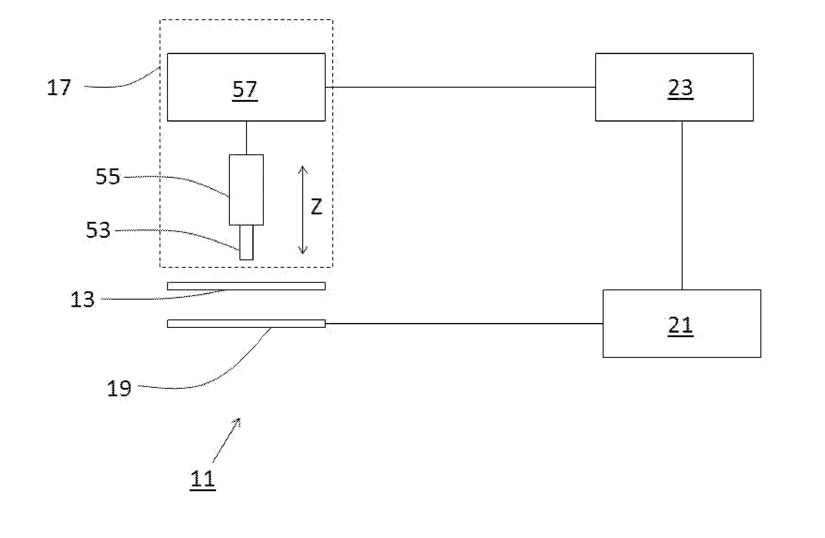
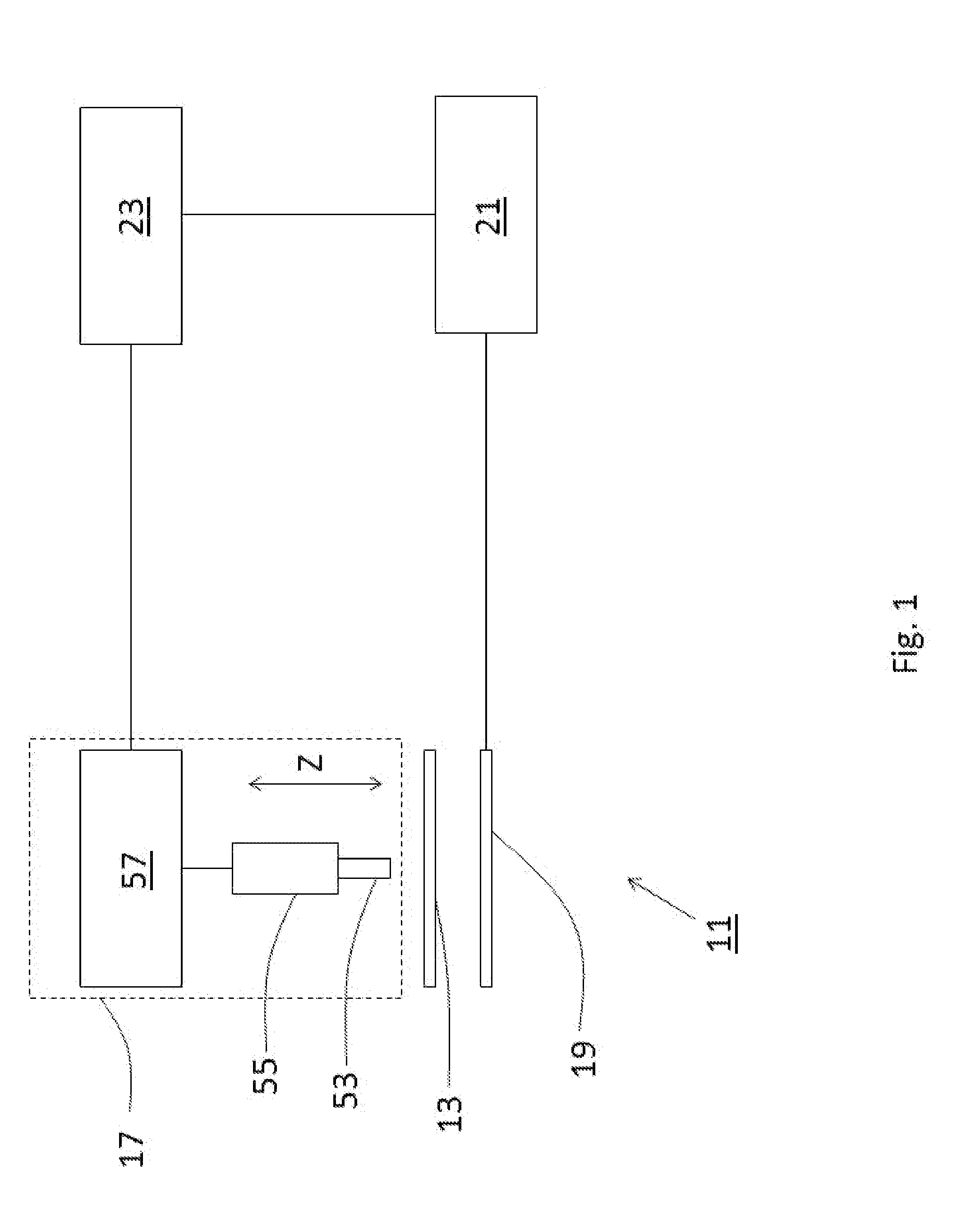
[0030]Referring now to FIG. 1, there is shown a system for detecting the depth of an antenna in the card body of a smart card, the system being constructed according to the teachings of the present invention and identified generally by reference numeral 11. As will be explained further in detail below, system 11 utilizes the natural resonance of the card body to accurately determine antenna depth.

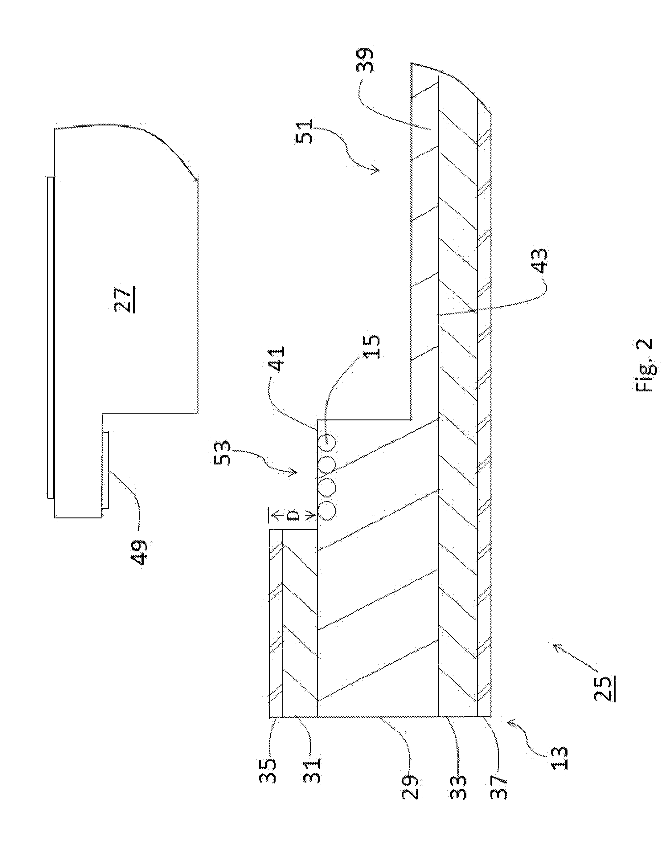
[0031]In the description that follows, system 11 is shown in use with a card body 13 with an embedded antenna 15. As defined herein, card body 13 represents any item that includes an embedded antenna 15, such as the card body for contactless and dual-interface smart cards.

[0032]Antenna detection system 11 comprises a milling device 17 for penetrating one surface of card body 13, a test device 19 disposed in close proximity to card body 13, a network analyzer 21 for measuring a linear characteristic of test device 19, and a control device 23 for regulating operatio...


PUM


Abstract

A system for detecting the depth of an antenna embedded in the card body of a smart card includes a milling device for forming a cavity in the card body, a test device disposed in close proximity to the card body, a vector network analyzer (VNA) for measuring a linear characteristic of the test device, and a control device for regulating operation of the milling device in view of data collected by the VNA. In use, the VNA generates a test signal and measures the degree of signal reflection from the test device. Under normal conditions, the VNA observes a spike in forward return loss at the natural resonant frequency of the open antenna circuit. However, at the instant that the milling device contacts the antenna, a notable variance in the degree of signal reflection is observed which indicates that the proper antenna depth has been reached.

Description

FIELD OF THE INVENTION[0001]The present invention relates generally to smart cards and, more particularly, to systems and methods for manufacturing smart cards that include an antenna.BACKGROUND OF THE INVENTION[0002]Smart cards are well known devices that include a card body into which is embedded an integrated circuit (IC). The integrated circuit is designed to store data that can be used, inter alia, to provide the card with electronic identification, authentication, data storage and application processing capabilities. As a result, smart cards, which are also commonly referred to as integrated circuit cards or chip cards, are widely used in commerce to provide information and / or application processing capabilities in connection with, but not limited to, bank cards, credit cards, health insurance cards, driver's licenses, transportation cards, loyalty cards and membership cards.[0003]Smart cards of the type as described above transmit data stored on the integrated circuit using e...

Claims


Application Information

Patent Timeline
IPC IPC(8): G06K19/07G01R29/10
CPCG01R29/10G06K19/0722G06K19/07754G01R29/0814
Inventor ZIEMKUS, THOMAS
Owner AMERICAN BANKNOTE
Why Eureka
Try Eureka