
Method and apparatus for transmitting an asynchronous transport signal over an optical section

a technology of optical transmission and optical section, applied in the field of telecommunications, can solve the problems of severe increase of problems, inability to tolerate, and inability to achieve the effect of reducing the number of optical transmission devices,

Active Publication Date: 2015-10-08
WSOU INVESTMENTS LLC
View PDF2 Cites 6 Cited by
  • Summary
  • Abstract
  • Description
  • Claims
  • Application Information

AI Technical Summary

Benefits of technology

The patent describes a method for encapsulating asynchronous transport signals by adjusting their bit rate to match the payload rate of outer transport frames. This process helps eliminate any unstable frequency or phase transients in the signal. The adjusted signal is then synchronously mapped into the outer frames at the same rate as the local clock. This technique ensures reliable and accurate transfer of information.

Problems solved by technology

The inventors have considered that with the introduction of coherent optical transmission, this problem is severely increased due to the fact that coherent optical receivers are sensitive to phase and frequency transients.
The impact on the network can thus be in the range of tens of milliseconds, which cannot be tolerated.

Method used


Image

  • Method and apparatus for transmitting an asynchronous transport signal over an optical section
  • Method and apparatus for transmitting an asynchronous transport signal over an optical section
  • Method and apparatus for transmitting an asynchronous transport signal over an optical section

Examples


Embodiment Construction

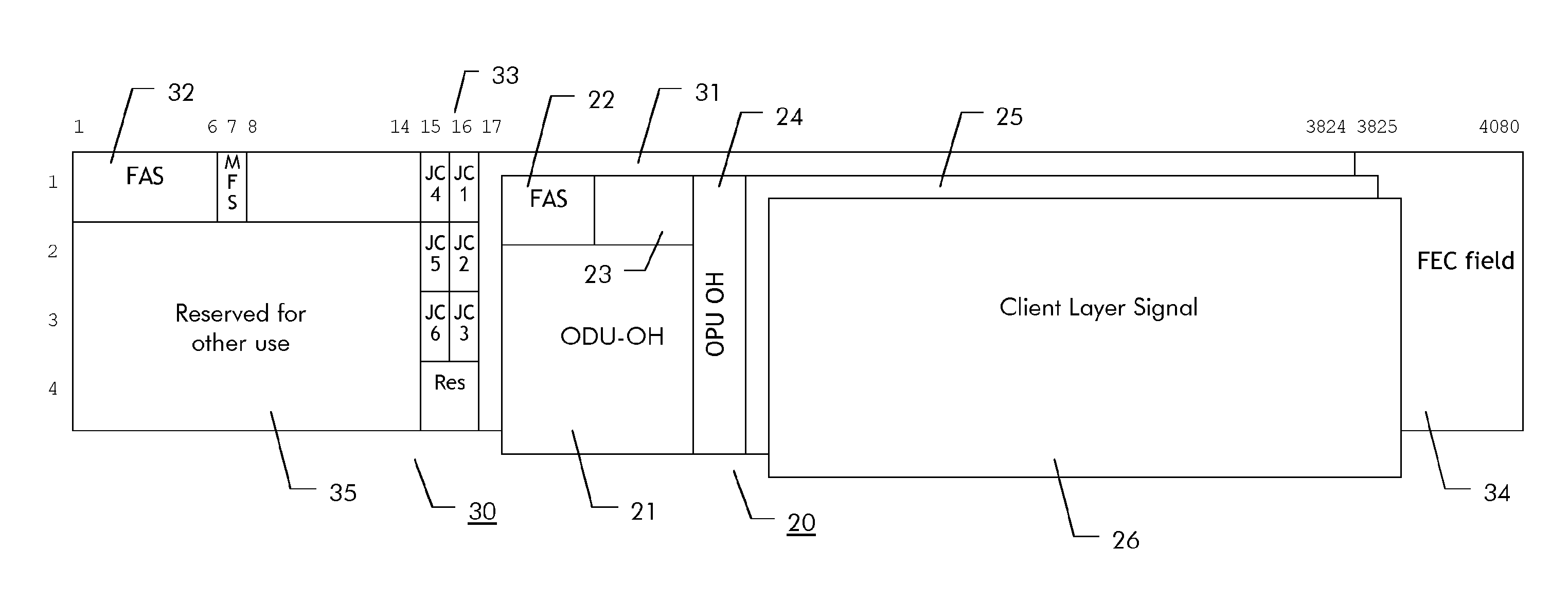
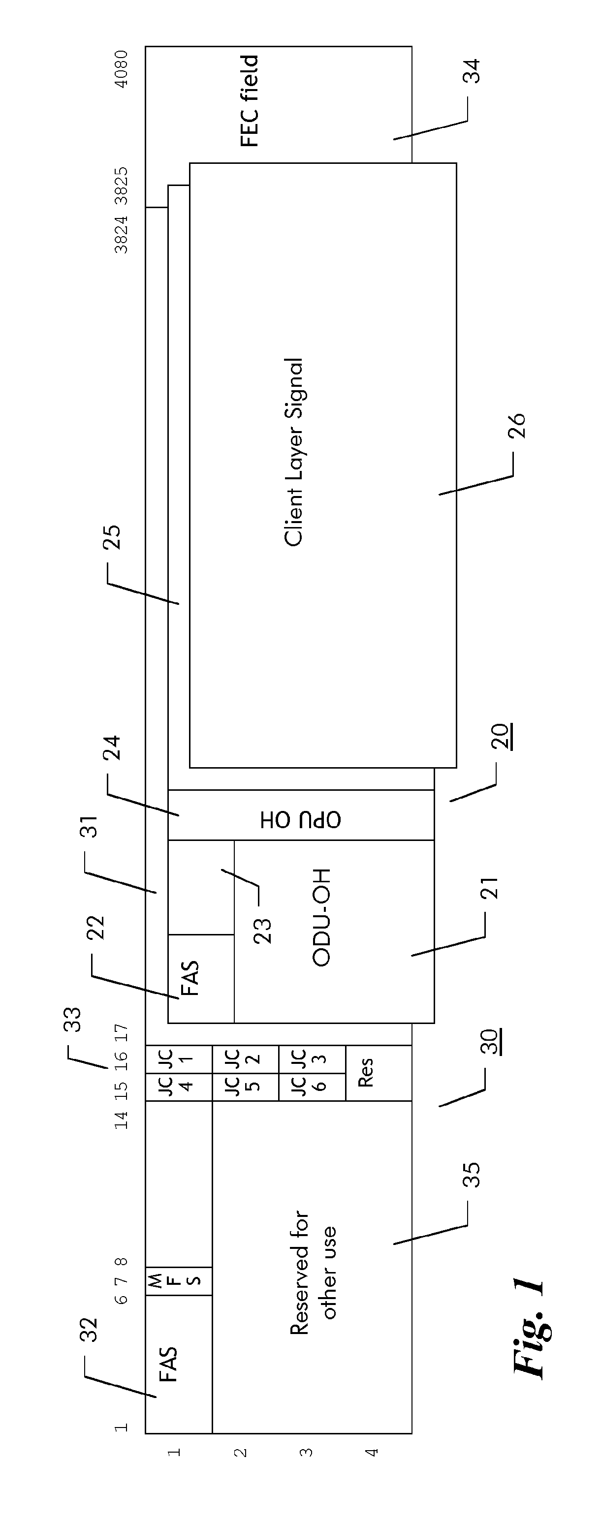
[0018]In OTN transmission in the case of phase transients of the OTU / ODU frame and clock, a frame phase or frequency transient will propagate through the network enforcing the different nodes in a chain to subsequently re-synchronize in terms of frame and frequency alignment. The reason is the fixed alignment of the OTUk to the ODUk frame. As to the bit synchronous mapping of an ODUk into the OTUk, also the optical transmission processes and synchronization will be affected by a frequency or frame phase transient. This will create a hit to the traffic and the re-synchronization time will be incremented at each node the transient passes. This effect is described also in ITU-T Rec. G.798 in a note in section 14.5.1.1.2 currently published in G.798 Amendment 2 (April / 2012).

[0019]Such transients appear in networks subsequent to sections affected by protection switches and / or switching to or clearing from replacement signals transport such as AIS or OCI. As explained before, this creates...


PUM


Abstract

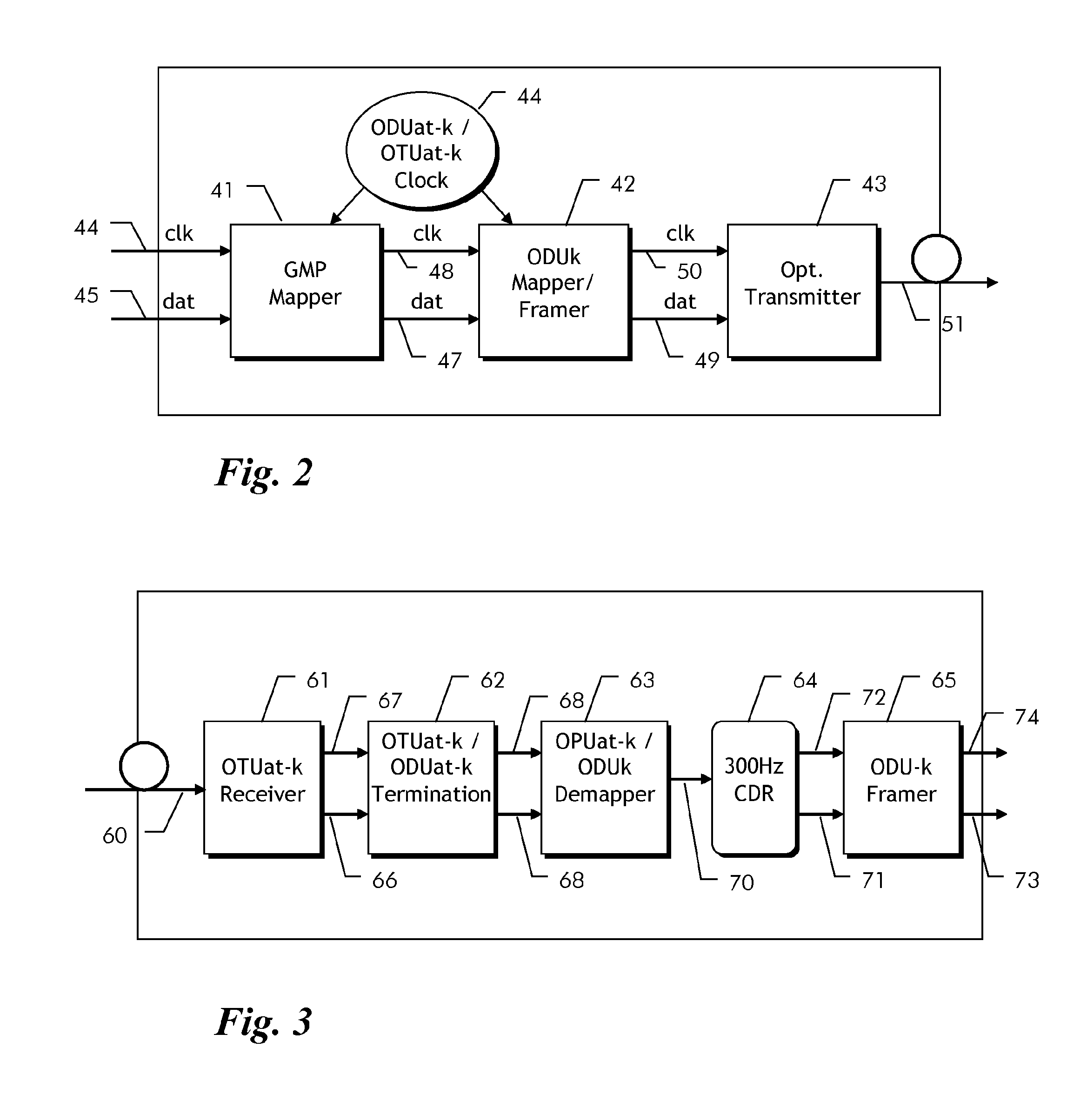
An exemplary method and apparatus are provided for transmitting an asynchronous transport signal over an optical fiber section of an Optical Transport Network. Higher order Optical Data Units of an asynchronous transport signal to be transmitted may be encapsulated into outer transport frames that offer a payload rate higher than a nominal bit rate of the asynchronous transport signal. An output optical signal, which contains the outer transport frames with the encapsulated asynchronous transport signal, is generated at a locally generated clock rate and transmitted over an optical fiber section. To encapsulate the asynchronous transport signal, its bit rate is adapted to the payload rate of the outer transport frames, which is derived from the locally generated clock through a justification and stuffing process. The rate adapted transport signal is then synchronously mapped into the outer transport frames at the rate of the locally generated clock.

Description

FIELD OF THE INVENTION[0001]The present invention relates to the field of telecommunications and more particularly to a method and related apparatus for transmitting optical signals in an Optical Transport Network.BACKGROUND OF THE INVENTION[0002]The ITU has defined in ITU-T G.709 the signals format and interfaces of the Optical Transport Network (OTN). The basic frame structure is an Optical Transport Module of size k (OTUk), where k can be 1, 2, 2e, 3, 3e2, or 4. It contains framing and section overhead plus a bit-synchronously mapped transport entity termed Optical Data Unit of size k (ODUk). An ODUk contains a payload area plus ODUk overhead. An Optical Payload Unit (OPUk) is mapped into the payload area and carries a client signal or other lower order ODUs being time-division multiplexed. OTUk signals are asynchronous within certain specified limits of typically ±20 ppm.[0003]To create an OTU frame, a client signal rate is first adapted at the OPU layer. The adaptation contains...

Claims


Application Information

Patent Timeline
Patent Type & Authority Applications(United States)
IPC IPC(8): H04L12/46H04J3/16H04B10/27
CPCH04L12/4633H04J3/1652H04B10/27H04J3/07H04J2203/0089
Inventor FRITSCHI, KLAUS-DIETERMEYER, GERHARDRAHN, JURGENTHOMAS, WOLFGANG
Owner WSOU INVESTMENTS LLC
Learn More