
Vibrating shoes, version 2

a technology of vibration shoes and shoes, applied in the field of vibration shoes, can solve the problems of achy feet, lack of portability, cumbersome machines, etc., and achieve the effects of convenient use, low cost, and simple structur

Inactive Publication Date: 2015-10-15
GOOD VIBRATIONS SHOES
View PDF8 Cites 8 Cited by
  • Summary
  • Abstract
  • Description
  • Claims
  • Application Information

AI Technical Summary

Benefits of technology

The present invention is a therapeutic vibrating shoe that has the following technical effects: (a) lightweight construction, (b) portability, (c) mobility, (d) available therapy in transit, (e) options for the user to remain seated while experiencing vibration, and (f) inexpensive, modular construction. The invention allows therapy to the common complaint of foot ache, while not encumbering the wearer to be non-active. The wearer can choose when and where they receive therapy for foot discomfort. The invention appears as regular high quality, dress, casual, and athletic shoes.

Problems solved by technology

Persons that stand for long periods or walk excessive distance during a normal day are subject to tired, achy feet which may be compounded by swelling.
The difficulty with each modality is the lack of portability, the machines being cumbersome and heavy, especially those that are filled with water.
Vibrating machines are heavy to move, difficult to store and require that the user be stationary during therapy sessions.
All of the aforementioned products are not practical for an active lifestyle or appropriate in the workplace.
In addition they are very expensive and occupy an unreasonable amount of space.

Method used


Image

  • Vibrating shoes, version 2
  • Vibrating shoes, version 2
  • Vibrating shoes, version 2

Examples


Embodiment Construction

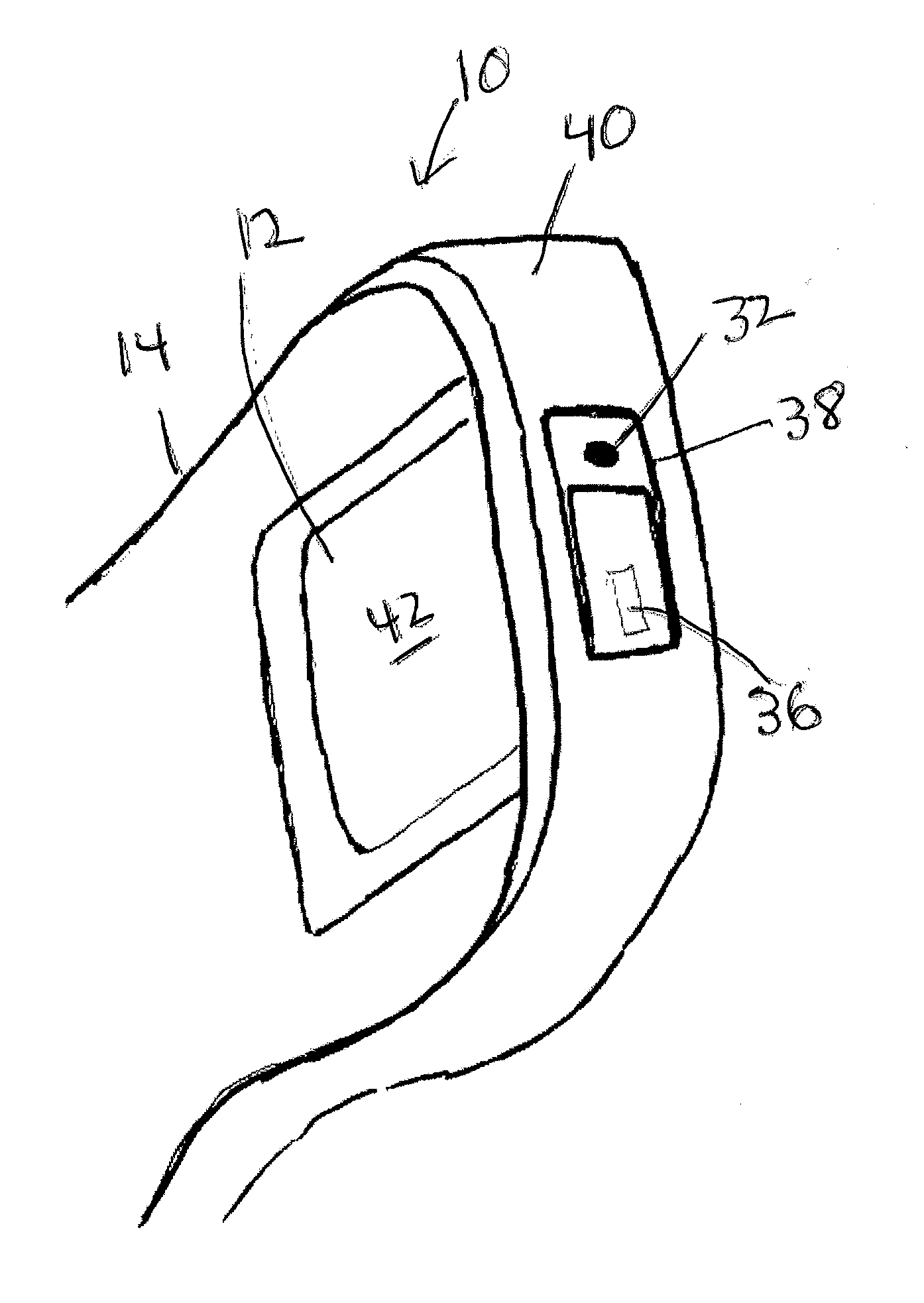
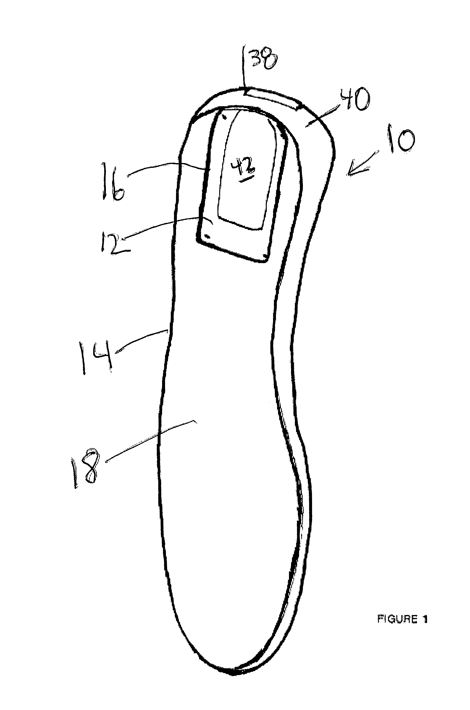
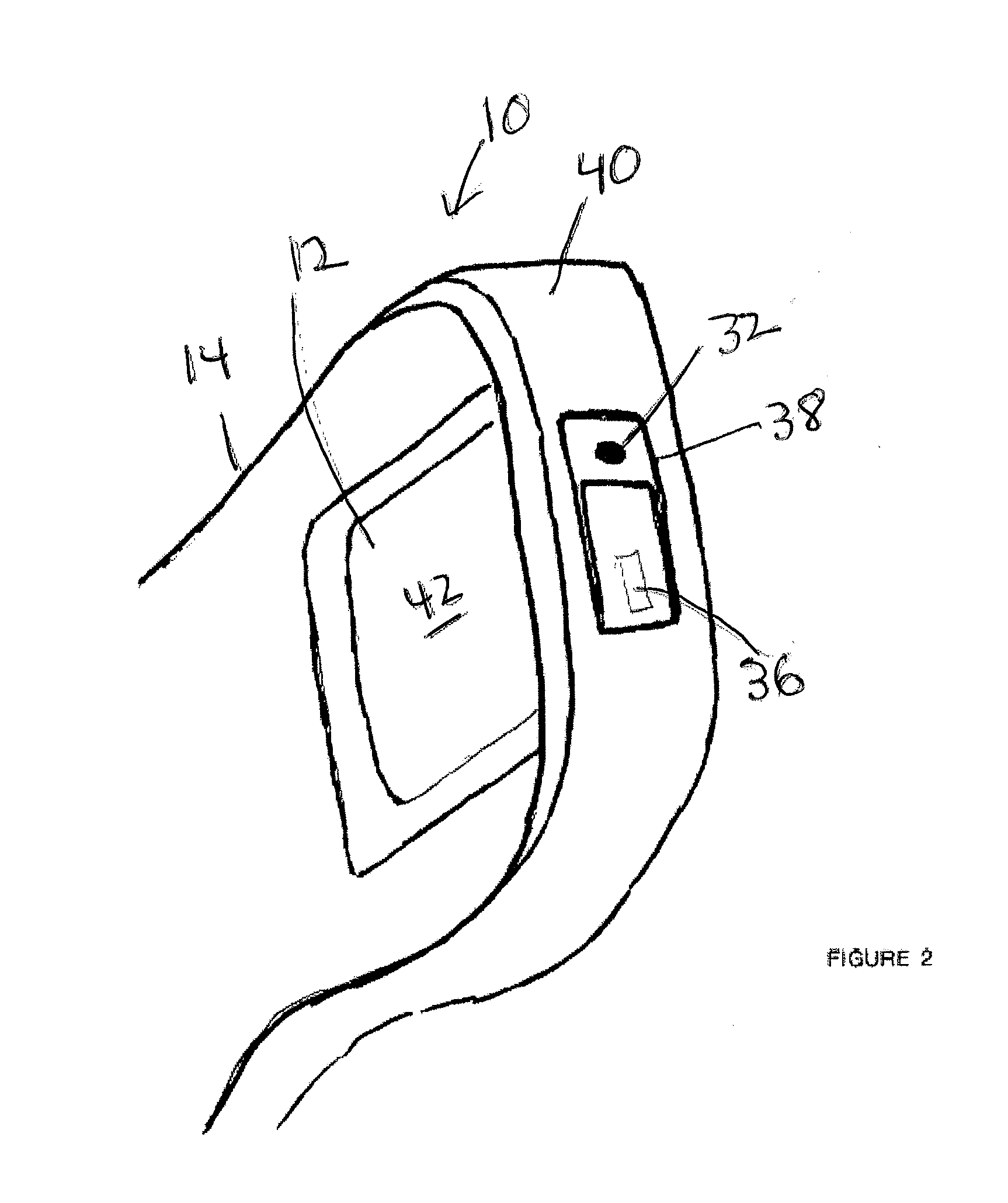
[0024]The present invention is a vibrating sole device, shown at 10 in FIGS. 1 through 4. The device comprises a vibration unit 12. The vibration unit 12 may be located in a sole 14 at a cavity 16 on the top surface 18 of the sole 14.

[0025]The vibration unit 12 includes a unitary housing 20 shown in FIGS. 4 and 5. The housing 20 includes an interior portion 22 and a heel portion 24. A vibrator 26 is located in the interior portion 22 of the housing 20. The vibrator may be a vibrating motor, and may have a frequency of about 5000 revolutions per minute.

[0026]A power supply 28 in direct or indirect electrical connection with the vibrator 26 is located in the interior portion 22 of the housing 20. An actuator 30 for the vibrator 26 such as a switch is also located at the interior portion 22 of the housing 20. The actuator 30 could be a push button or a sliding switch. The actuator 30 is directly or indirectly electrically coupled to the vibrator 26. In addition, the device 10 includes ...


PUM


Abstract

A vibrating sole device, comprising a vibration unit located within a cavity in a sole, comprising a unitary housing having an interior portion and a heel portion, a vibrator located at the interior portion of the housing, a power supply located at the interior portion of the housing in electrical connection with the vibrator, an actuator for said vibrator in the housing, a status indicator located on the heel portion of the housing, and a power supply port located on the heel portion of the housing.

Description

CROSS-REFERENCE TO RELATED APPLICATION[0001]This application relates to the same subject matter as co-pending provisional patent application Ser. No. 61 / 810,394, filed by the same applicant on Apr. 10, 2013. This application claims the Apr. 10, 2013 filing date as to the common subject matter.BACKGROUND[0002]1. Field of Invention[0003]This invention relates to shoes and devices with health improving features for those persons who experience cold, tired and achy feet along with persons to whom stimulation to the balance sensing nerve organs would be a benefit. The invention is an improved way to bring comfort to the mentioned conditions, with the advantage of portability while allowing ambulation.[0004]2. Related Art[0005]Persons that stand for long periods or walk excessive distance during a normal day are subject to tired, achy feet which may be compounded by swelling. Traditionally, these persons will desire the removal of their shoes at the earliest opportunity. Often they have s...

Claims


Application Information

Patent Timeline
IPC IPC(8): A61H23/00A43B13/00
CPCA43B13/00A61H23/00A43B3/0031A43B7/146A61H23/02A61H2201/164A61H2201/165A61H2201/5035A61H2205/12A43B3/36A43B3/38
Inventor KOENIG, RICHARD DONALD
Owner GOOD VIBRATIONS SHOES
Learn More