
Push-coil steering mechanism

a steering mechanism and push-coil technology, applied in the field of push-coil steering mechanism, can solve the problems of increasing moving steering wires, increasing friction, etc., and achieve the effect of reducing the risk of steering wire breaking and preventing undesirable friction

Active Publication Date: 2015-10-15
ST JUDE MEDICAL ATRIAL FIBRILLATION DIV
View PDF4 Cites 0 Cited by
  • Summary
  • Abstract
  • Description
  • Claims
  • Application Information

AI Technical Summary

Benefits of technology

The handle assembly described here prevents friction and damage to the steering wires by using a rotational actuator to control linear movement in a medical device. This means that the steering wires are always in a linear orientation, which reduces the risk of them breaking or getting tangled up with other surfaces.

Problems solved by technology

Rotation of the body causes movement of the steering wires.
Bending of the wires leads to an increase in friction between the wires and surfaces engaged by the wires within the catheter or sheath and increases the chance that a steering wire will break.

Method used


Image

  • Push-coil steering mechanism
  • Push-coil steering mechanism
  • Push-coil steering mechanism

Examples


Embodiment Construction

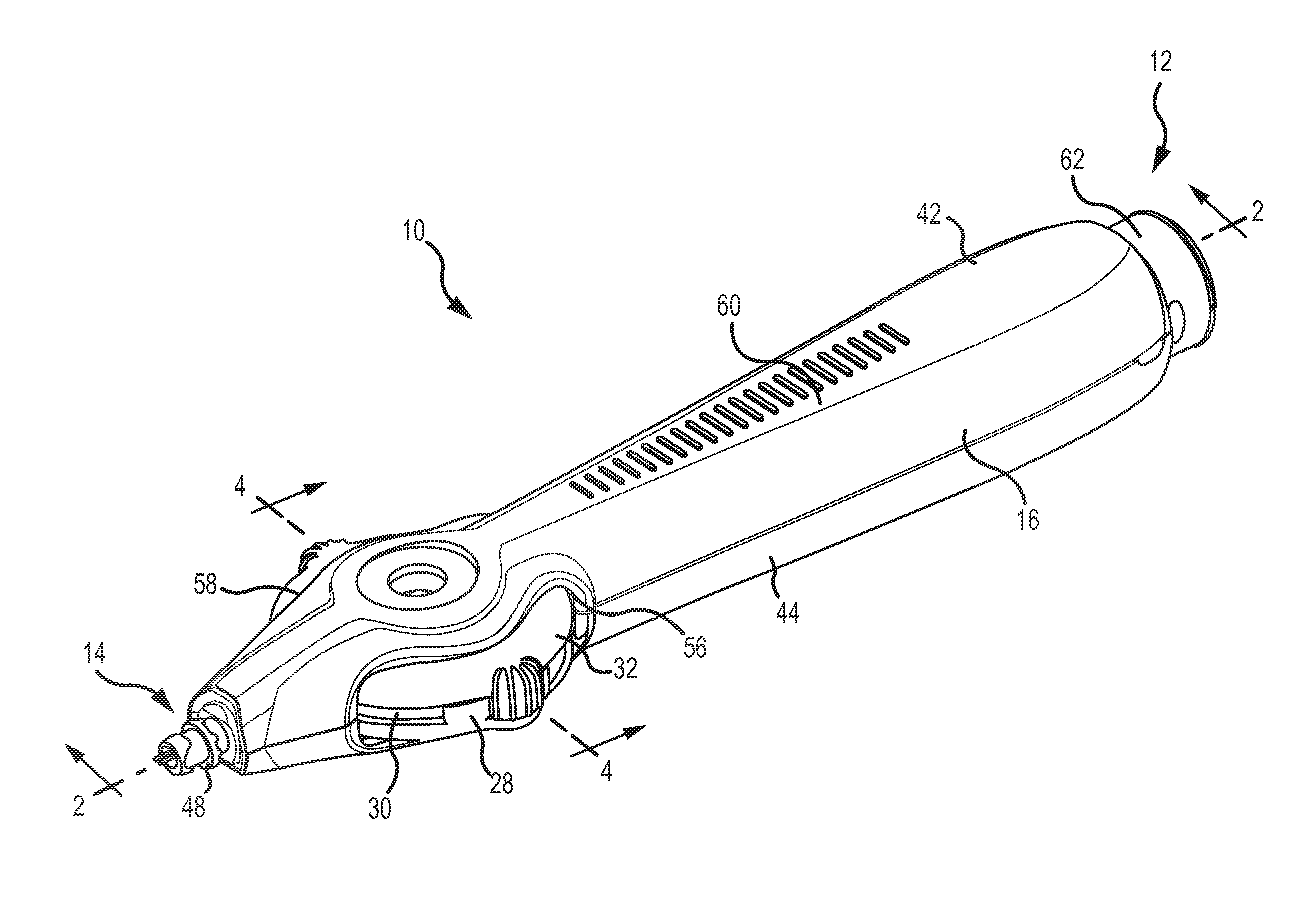
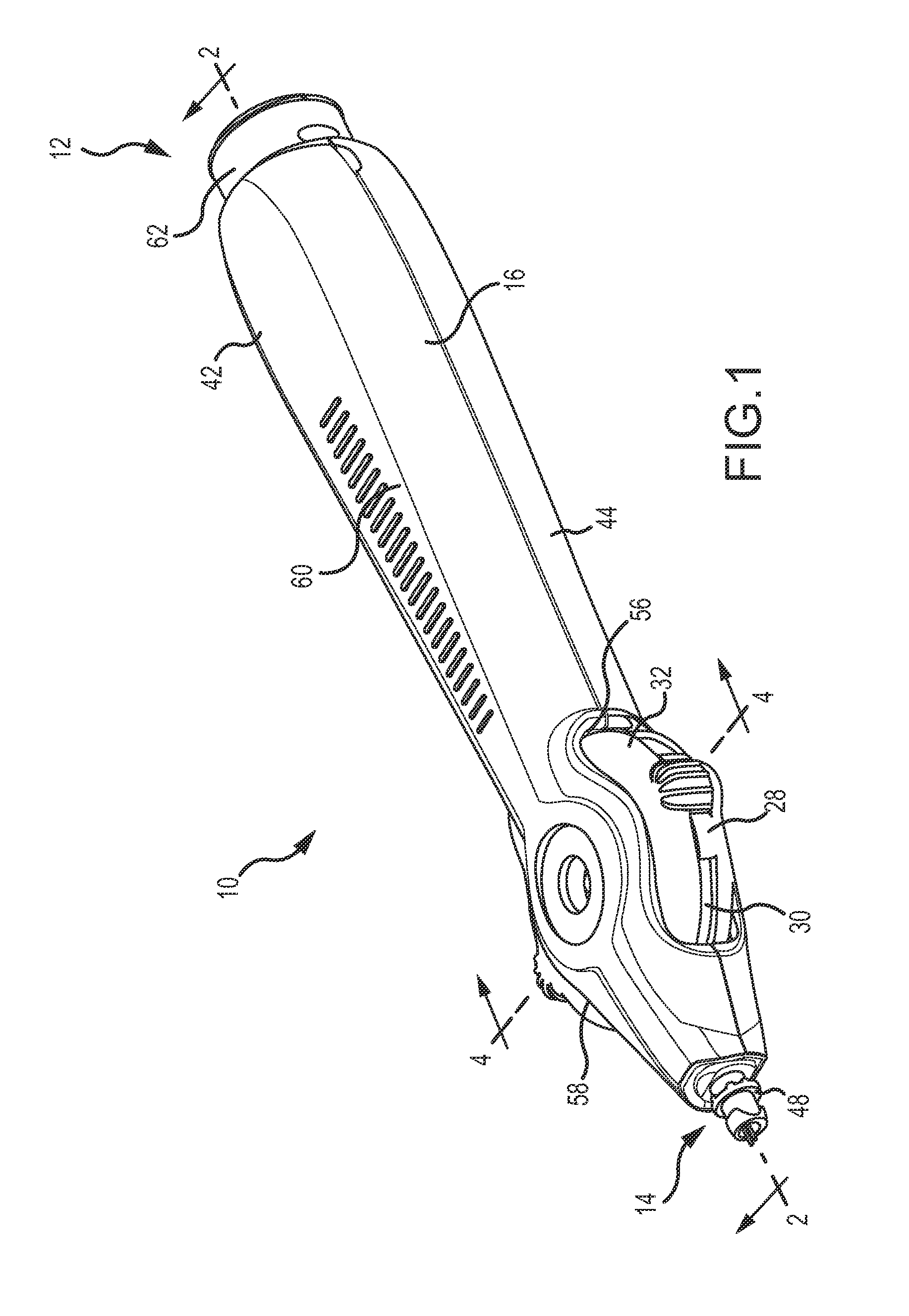
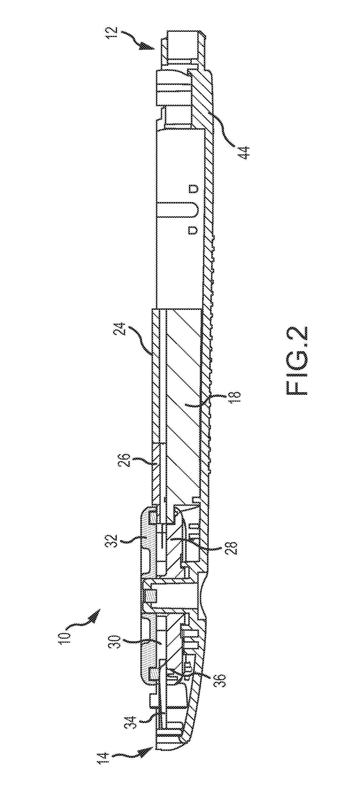
[0022]Referring now to the drawings wherein like reference numerals are used to identify identical components in the various views, FIGS. 1-3 illustrate one embodiment of a handle assembly 10 for use in navigating a deformable shaft (not shown) of a medical device within a body. The medical device may comprise, for example, a catheter (such an electrophysiological (EP) mapping catheter or an ablation catheter used in diagnosis or treatment of cardiac tissue within the body) or an introducer sheath. It should be understood, however, that a handle assembly 10 in accordance with the present teachings may find application in connection with a wide variety of medical devices used within body 12 for diagnosis or treatment. The deformable shaft of the medical device is typically an elongate, flexible, tubular member configured for movement within the body. The shaft may be made from conventional materials such as polyurethane and defines one or more lumens configured to house and / or transp...


PUM


Abstract

A handle assembly is provided for use in navigating a deformable shaft within a body. The assembly includes a first guide member defining first and second linear channels and a second guide member configured for rotation relative to the first guide member. First and second connectors are disposed within, and movable within, the first and second linear channels along first and second parallel axes, respectively, and are configured for coupling to first and second steering wires, respectively. The assembly includes means, such as a flexible coupling connected to the second guide member and the connectors, for translating rotation of the second guide member into linear movement of the first connector in a first axial direction and linear movement of the second connector in a second axial direction, opposite the first axial direction such that the first and second steering wires move in opposite directions.

Description

CROSS-REFERENCE TO RELATED APPLICATIONS[0001]This application is a continuation of U.S. application Ser. No. 13 / 663,569, filed 30 Oct. 2012, now pending, which is hereby incorporated by reference as though fully set forth herein.BACKGROUND OF THE INVENTION[0002]a. Field of the Invention[0003]This invention relates to introducer sheaths, catheters and other devices configured to be maneuvered through a body. In particular, the invention relates to an improved handle assembly for use in navigating a deformable shaft of such a device within a body.[0004]b. Background Art[0005]A wide variety of medical devices are inserted into the body to diagnose and treat various medical conditions. Catheters, for example, are used to perform a variety of tasks within human bodies and other bodies including the delivery of medicine and fluids, the removal of bodily fluids and the transport of surgical tools and instruments. In the diagnosis and treatment of atrial fibrillation, for example, catheters...

Claims


Application Information

Patent Timeline
Patent Type & Authority Applications(United States)
IPC IPC(8): A61M25/01
CPCA61M2025/015A61M25/0147A61M25/0136A61B1/00133
Inventor TEGG, TROY T.
Owner ST JUDE MEDICAL ATRIAL FIBRILLATION DIV
Learn More