Adaptive Precision Chuck

a precision chuck and chuck technology, applied in the direction of chucks, manufacturing tools, mechanical equipment, etc., can solve the problems of machining errors and tolerance issues, affecting the accuracy of chucks, etc., to prevent unnecessary friction and tolerance issues, simplify and ease user operations

Active Publication Date: 2021-04-15
BRUNEL UNIVERSITY
View PDF0 Cites 0 Cited by
  • Summary
  • Abstract
  • Description
  • Claims
  • Application Information

AI Technical Summary

Benefits of technology

[0018]As a result of using flexures, a chuck according to embodiments of the present invention can be manufactured as a single integrated device. This prevents the unnecessary friction and issues with tolerances that arise in multi-part device assemblies.
[0019]Embodiments are particularly suited to simplifying and easing user operations during machining setup for mass production, particularly in ultraprecision production of contact lens moulds. Preferred embodiments are integrated with or mountable to a vacuum chuck system such that vacuum forces are applied via the vacuum chuck to the adaptive chuck. A further embodiment is directed to a vacuum chuck diamond turning machine, which uses the vacuum forces as the actuation drive for clamping displacement.

Problems solved by technology

During machining, one or both of the chuck and tool are typically rotated about the common axis and if the workpiece is not centred or its position unintentionally deviates during machining, errors and defects in machining and / or damage to the workpiece may arise.
It will be appreciated that if elements that impact the optical profile such as the lens curvature is out by even microns, it potentially undermines the correction intended to be provided.
Where there is a misalignment, it leads to concentrically unequal off-centre movement (runout), which can further cause the machining errors and the cutting tool wear (or uneven cutting tool wear).
In the case of vacuum chucks, misalignment can arise during the machining process if the machining force overcomes the clamping force.
However, these reduce the flexibility of the machining system and increase costs.
Typically, these often complex to manufacture and use and comprise of many components.
Generally they are not cost-effective.
While these reduce misalignment and runout, setup can be time-consuming, the clamping devices complex and made from numerous moving parts and therefore expensive to manufacture

Method used


Image

  • Adaptive Precision Chuck
  • Adaptive Precision Chuck
  • Adaptive Precision Chuck

Examples


Embodiment Construction

[0042]Unless otherwise stated, common reference numerals amongst the illustrations refer to the same or corresponding features. It will, however, be appreciated that the particular size and layout of the body of the chuck, and the positioning and number of flexures can be varied while still providing the same self-centering and self-locking functionality.

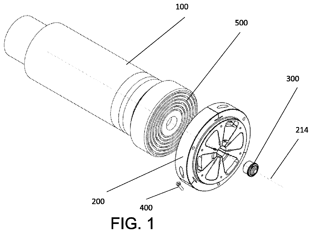
[0043]FIG. 1 is a perspective view of a spindle assembly including an adaptive chuck according to an embodiment of the present invention.

[0044]The Spindle assembly includes a spindle 100 and a vacuum chuck 500 that are attached to, or part of, a diamond turning machine or other similar precision machining system. The adaptive chuck 200 is mounted on the vacuum chuck 500 and is preferably fastened in location, in this example by three socket head cap screws 400. The adaptive chuck 200 and spindle 100 have a common axis 214 about which the spindle is rotated during operation.

[0045]The adaptive chuck 200 has a body and defines a mount....


PUM

PropertyMeasurementUnit
rotational forcesaaaaaaaaaa
forceaaaaaaaaaa
forcesaaaaaaaaaa

Abstract

An adaptive precision chuck for a precision/ultraprecision machining system is described. The chuck (200) defining a mount for receiving a workpiece (300) wherein, when in use, the centre of the mount is configured to be substantially concentric with an axis of rotation (214) of the machining system, the chuck (200) further including jaws (210) about the mount and a plurality of compliant flexures (203-206) configured, upon application of rotational forces by the machining system to the chuck about the axis of rotation (214), to engage the jaws (210) upon a workpiece (300) in the mount.

Description

CROSS-REFERENCE TO RELATED APPLICATION[0001]This application claims priority to GB Patent Application No. 1914672.9 filed Oct. 10, 2019, the contents of which are incorporated by reference in its entirety as if set forth herein.FIELD OF THE INVENTION[0002]The present invention relates to an adaptive precision chuck that is particularly applicable for use in high precision engineering and machining.[0003]BACKGROUND TO THE INVENTION[0004]Chucks are often used to hold and position workpieces while they are being machined using spindle-based tools such as lathes. Typically, the intention is for the chuck to securely retain the workpiece in place so that there is a shared common axis between a designated centre of the workpiece and the tool. During machining, one or both of the chuck and tool are typically rotated about the common axis and if the workpiece is not centred or its position unintentionally deviates during machining, errors and defects in machining and / or damage to the workpi...

Claims


Application Information

Patent Timeline
Patent Type & Authority Applications(United States)
IPC IPC(8): B23B31/14
CPCB23B31/142B23B2231/22B23B31/14B23B31/307B23B31/36B23B31/102B23B2270/06B23B31/18B23Q3/065B23Q3/067Y10T279/247
Inventor CHENG, KAIKHAGHANI, ALI
Owner BRUNEL UNIVERSITY
Why Eureka
Try Eureka