The pressure within the chamber may also leak over time and be insufficient to propel the
powder out of the dispensing
nozzle.
A further limitation, based upon this design is due to the pressurized condition of the chamber,
powder is placed into the chamber in a small opening in the top of the extinguisher.
They cannot in fact meet the standards required of them.
They cannot meet the requirements of the UL
label.
Nor can they meet the manufacturer's requirements.
There are no service vehicles capable of carrying a
recovery system for each brand of extinguisher as required by UL.
All extinguishers in service today have contaminated powder and the UL has been voided.
The manufacturer and NFPA-10 standards also impose standards that cannot be met by the service firms.
The current system is plagued with serious problems.
The service firms have very little supervision and are in a position to abuse the public.
Most
enforcement officers are charged with other more serious duties, i.e. arson etc. and has little time to dedicate to a system that is in fact impossible to maintain.
The vast majorities of service firms operate out of the back of their trucks and are continually on the move, making them difficult to locate and to implement any type of
enforcement.
Another limitation with portable fire extinguishers that are currently available is that the fire extinguishers can only be shipped by land because they are pressurized, and could rupture when they are shipped by air.
The servicing of current fire extinguishers often creates more
wear and tear on the fire extinguisher than when it is used to extinguish a fire.
While these patents disclose a separate pressurized canister, the canister is not located in a position that is easy to service, replace, or inspect.
It is known that one of the problems with powder type fire extinguishers is the possibility that the extinguishing powder within the chamber can cake and harden if it is not fluffed to keep the powder in liquid configuration.
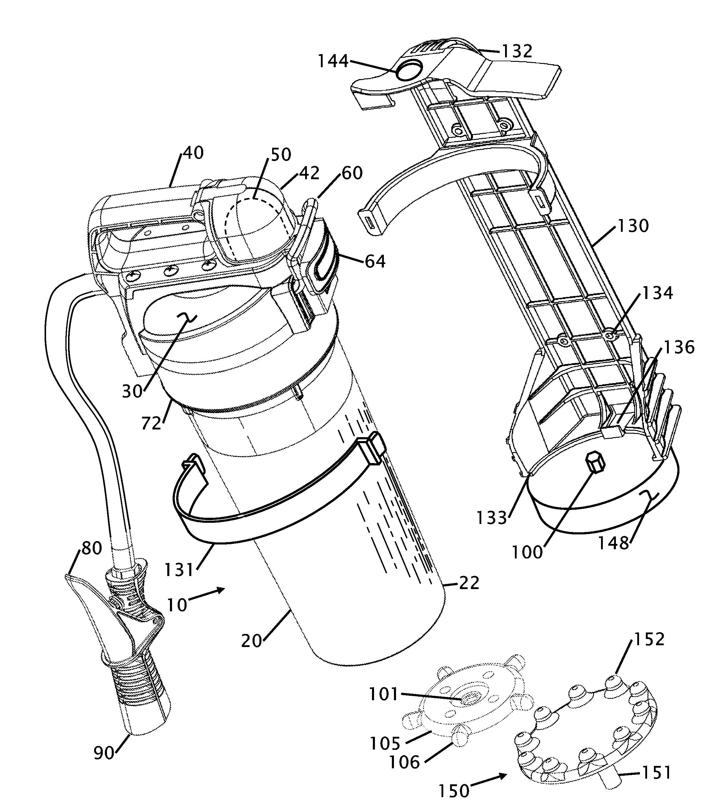
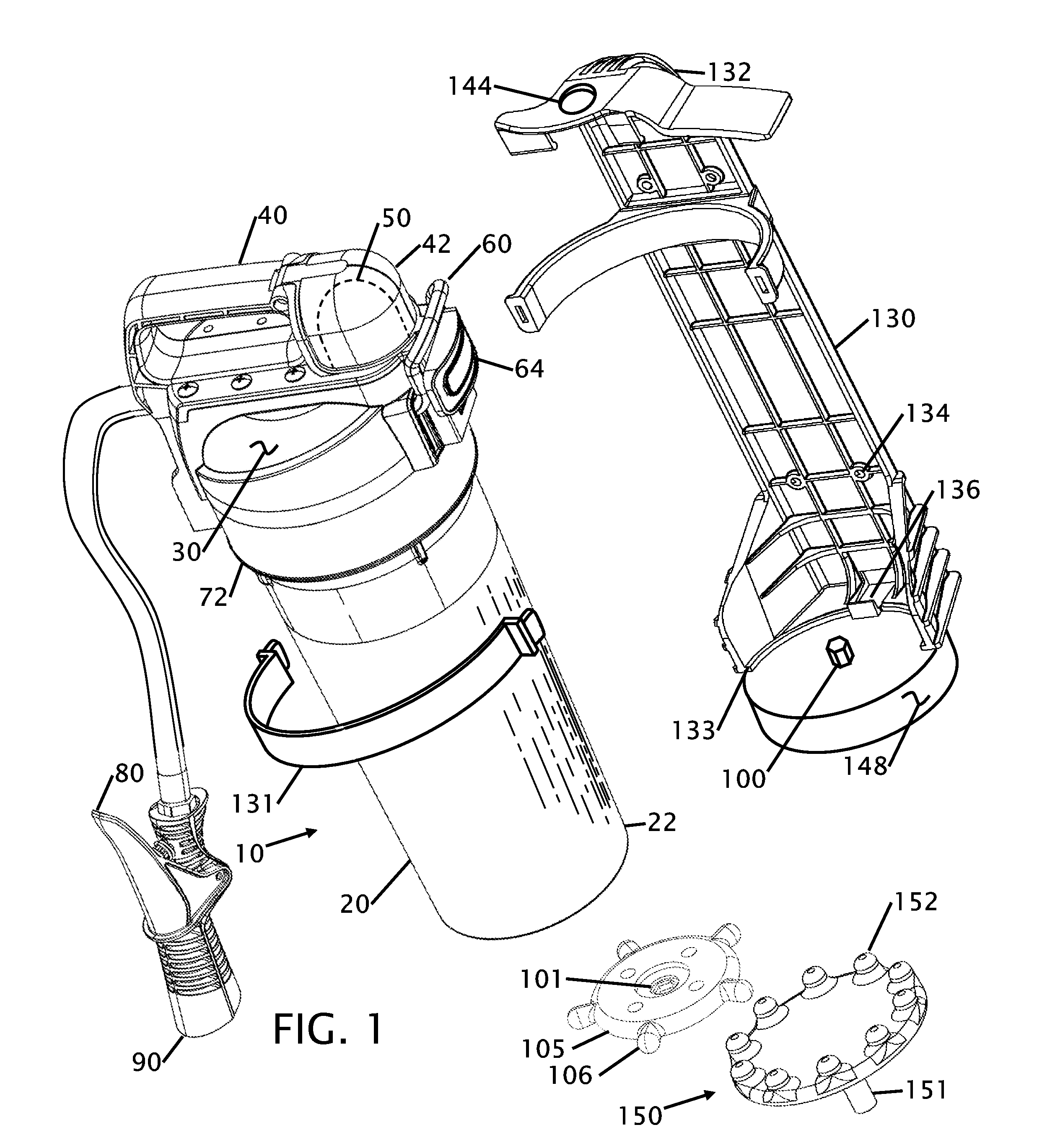
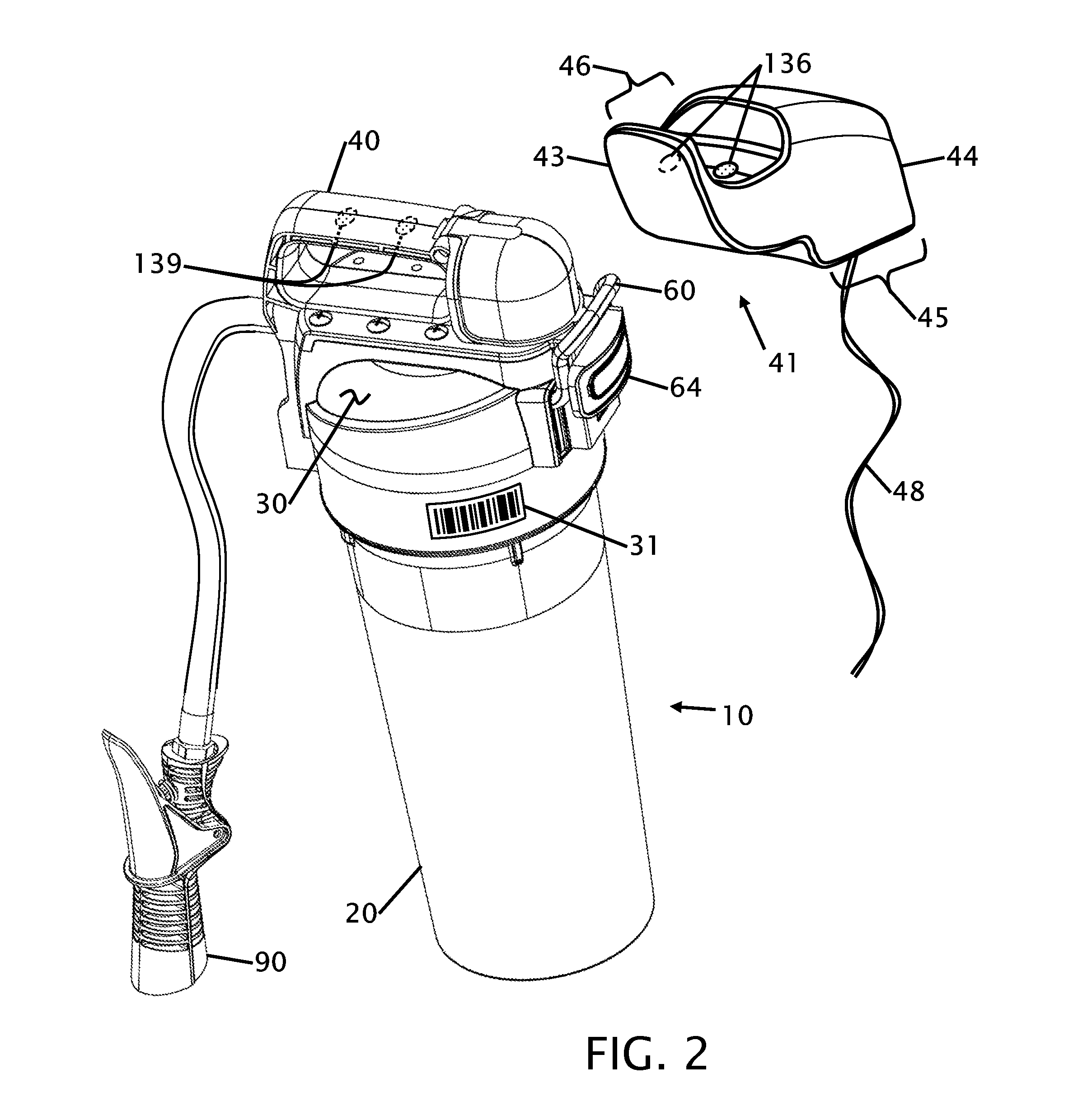
Due to the pressurized condition that exists with pressurized fire extinguishers, the opening where powder is placed into the extinguisher is limited due to the structural requirement to maintain pressure within the chamber at all times. The proposed application eliminates this need by providing an external pressurized gas
cartridge, thus allowing the chamber to exist in a normally un-pressurized condition.
While these patents disclose a signaling means to announce that the fire extinguisher has been removed, none of them disclose a
wireless indicator, or due they provide for a mixing mechanism for fluffing the internal contents of the fire extinguisher.

