Automated concrete structural member fabrication method

a technology of automatic concrete and structural members, applied in the field of construction, can solve the problems of structural inferiority to those created with larger structures, difficulty in the fabrication process, and the discussion of precast wall units, and achieve the effect of moderate size and complexity, efficient and streamlined

Active Publication Date: 2015-10-15
SPEEDBLOCK INC
View PDF5 Cites 4 Cited by
  • Summary
  • Abstract
  • Description
  • Claims
  • Application Information

AI Technical Summary

Benefits of technology

[0014]An advantage of the present invention is that it provides an efficient and streamlined system for manufacture of modular precast blocks.
[0015]Another advantage of the present invention is that it provides an apparatus of moderate size and complexity for casting modular precast blocks.
[0016]And another advantage of the present invention is that it provides an apparatus which includes a conveying system for the cast modular precast blocks
[0017]A further advantage of the present invention is that it provides an apparatus which includes a simple means of removing the cast modular blocks from the molding device.
[0018]A yet further advantage is that the present invention incorporates the casting, removal and conveying of the modular precast blocks in a single system.
[0019]Yet another advantage of the present invention is that the system is expandable to accommodate multiple casting machines, which can be served by a concrete delivery system.

Problems solved by technology

While concrete masonry units (CMUs) may be designed for a variety of applications, they can result in structures that are structurally inferior to those created with larger, reinforced concrete units.
As a result, larger precast blocks are being used, but generally the larger the precast block, the more difficult the fabrication process.
The precast wall units discussed in this patent are of much larger size and complexity than the simple CMUs previously used.
As one might expect, the sheer size and weight of larger-scale precast units present unique problems in their manufacture.

Method used


Image

  • Automated concrete structural member fabrication method
  • Automated concrete structural member fabrication method
  • Automated concrete structural member fabrication method

Examples


Embodiment Construction

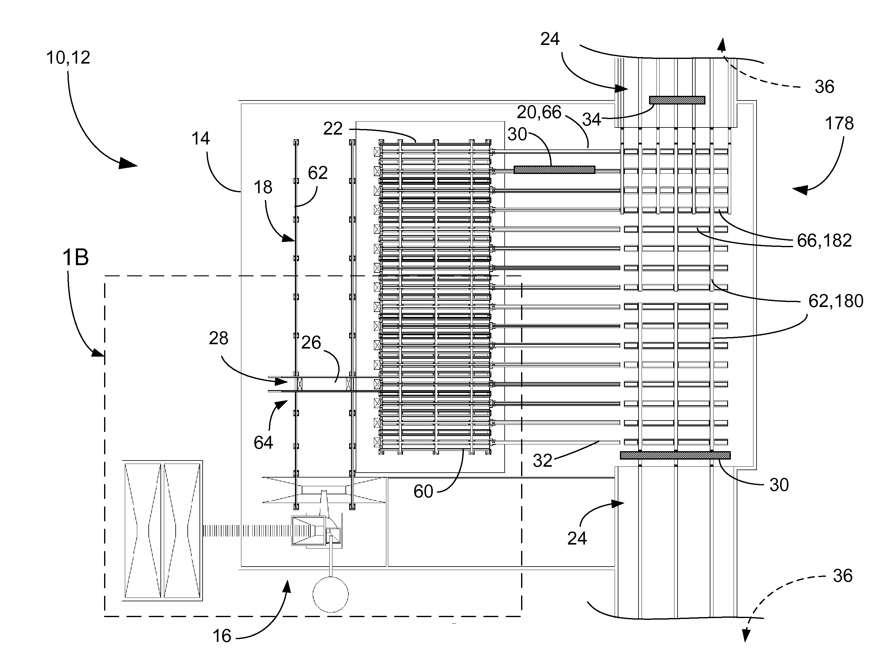
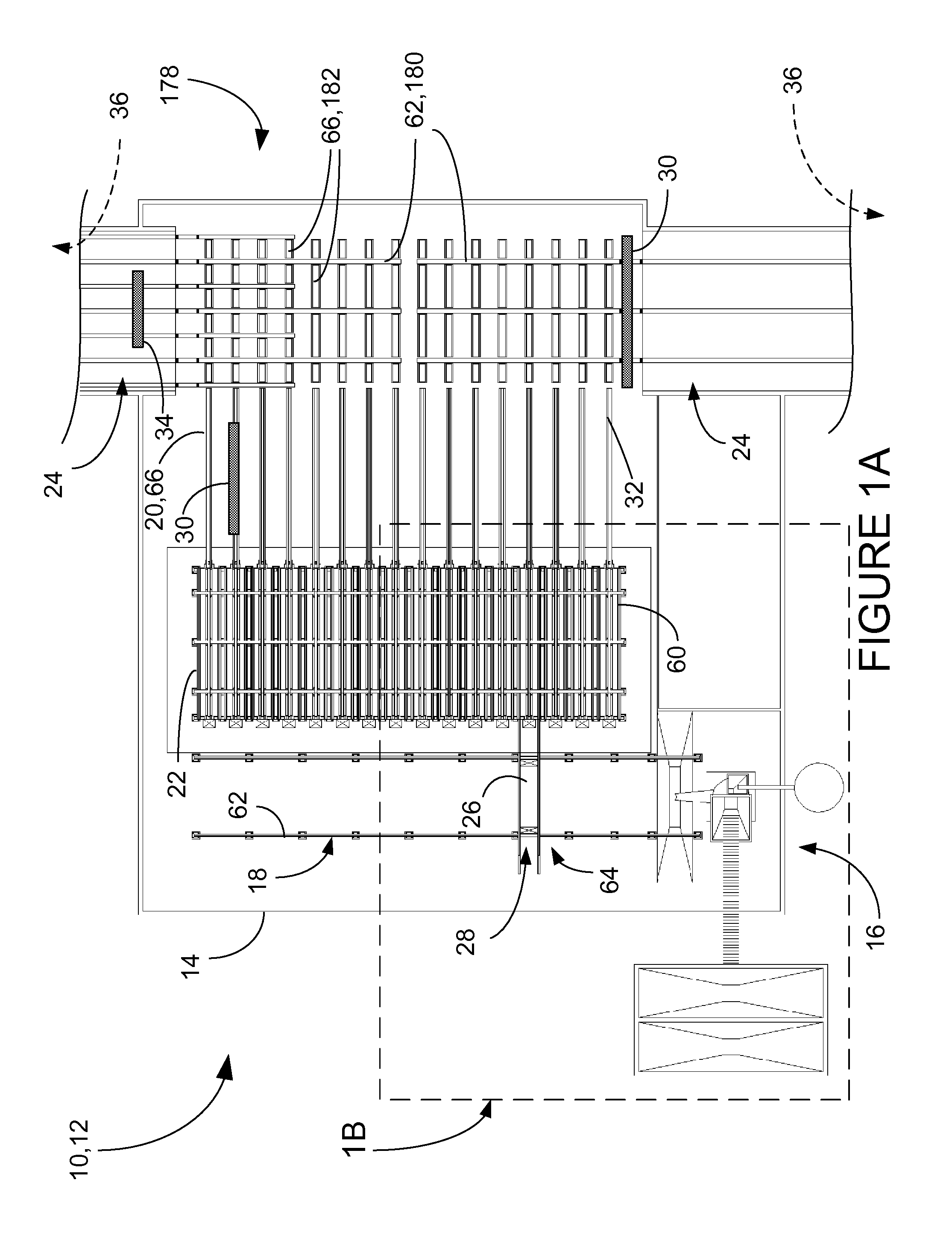
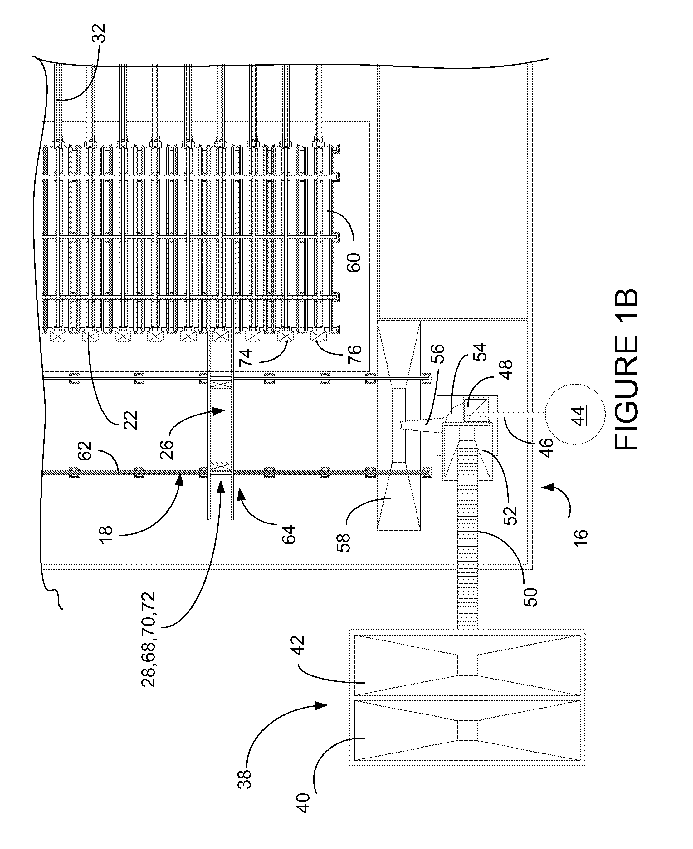
[0041]A presently preferred embodiment of the present invention is a system for manufacture of precast concrete structural members. An overhead plan view of the preferred embodiment is the fabrication system illustrated in FIGS. 1A and B and the other figures of the drawings and is designated by the general reference character 10. The system of the present invention 10 provides an automated system for the fabrication of precast modular blocks for building construction, which is highly efficient and allows the production of much greater numbers of precast modular blocks of a larger size then is possible by use of prior casting equipment and methods.

[0042]The purpose of the fabrication system 10 is to create precast block units of the type illustrated in FIG. 2. The typical precast block unit shown in perspective view in FIG. 2 is designated by the reference number 1. As shown, the block unit 1 is laterally symmetrical and includes a first sidewall 2 and a second sidewall 3, situated ...


PUM

PropertyMeasurementUnit
sizeaaaaaaaaaa
weightaaaaaaaaaa
flexibleaaaaaaaaaa

Abstract

A method of fabrication for precast concrete structural members, including providing an automated concrete structural member fabrication system, including at least one casting machine having a self-releasing mold which includes side walls and end dams which are pivotally movable from an open position to a closed position, and a bottom casting surface, where the bottom casting surface, the side walls, and the end dams surround a cavity when the side walls and the end dams are in closed position, and a removable mold core subsystem which is removably positionable within the cavity; moving the mold sides, the mold end dams and the bottom casting surfaces to a closed position; positioning the mold core subsystem within the cavity; filling the cavity with wet concrete; idling the casting machine until the wet concrete has achieved initial set to form an initial set concrete block; automatically releasing the self-releasing mold from the initial set concrete block; and removing the initial set concrete block from the casting machine.

Description

[0001]The present application is a continuation of and claims priority to currently pending application Ser. No. 12 / 957700, filed Dec. 1, 2010 entitled AUTOMATED CONCRETE STRUCTURAL MEMBER FABRICATION SYSTEM, APPARATUS AND METHOD, by the present inventors.TECHNICAL FIELD[0002]The present invention relates generally to the field of construction, and more particularly to apparatus for manufacturing precast blocks for the construction of walls and other structures.BACKGROUND ART[0003]Precast concrete structural members are becoming increasingly known and used to create buildings or other structures. These precast structural members include blocks, foundation elements and partial wall units and incorporate a wide range of precast block designs that vary from the simple to the very complex. The most elementary precast block designs are those used in basic, concrete masonry, such as the well-known “cinder block”. While concrete masonry units (CMUs) may be designed for a variety of applica...

Claims


Application Information

Patent Timeline
Patent Type & Authority Applications(United States)
IPC IPC(8): B28B7/10E04C2/04E04C1/00B28B7/22
CPCB28B7/10E04C1/00E04C2/04B28B7/22B28B7/0044B28B7/183B28B7/285B28B13/026B28B15/00B28C1/003
Inventor GARFINKEL, ERIKMACMILLAN, JOHN R.
Owner SPEEDBLOCK INC
Why Eureka
Try Eureka