Concrete delivery subsystem for automated concrete fabrication system

a technology of concrete and delivery subsystem, applied in the field of construction, can solve the problems of reinforced concrete units, precast wall units discussed, and structures that are structurally inferior to those created with larger, and achieve the effects of moderate size and complexity, efficient and streamlined

Active Publication Date: 2016-08-16
SPEEDBLOCK INC
View PDF3 Cites 4 Cited by
  • Summary
  • Abstract
  • Description
  • Claims
  • Application Information

AI Technical Summary

Benefits of technology

[0014]An advantage of the present invention is that it provides an efficient and streamlined system for manufacture of modular precast blocks.
[0015]Another advantage of the present invention is that it provides an apparatus of moderate size and complexity for casting modular precast blocks.
[0016]And another advantage of the present invention is that it provides an apparatus which includes a conveying system for the cast modular precast blocks
[0017]A further advantage of the present invention is that it provides an apparatus which includes a simple means of removing the cast modular blocks from the molding device.
[0018]A yet further advantage is that the present invention incorporates the casting, removal and conveying of the modular precast blocks in a single system.
[0019]Yet another advantage of the present invention is that the system is expandable to accommodate multiple casting machines, which can be served by a concrete delivery system.

Problems solved by technology

While concrete masonry units (CMUs) may be designed for a variety of applications, they can result in structures that are structurally inferior to those created with larger, reinforced concrete units.
As a result, larger precast blocks are being used, but generally the larger the precast block, the more difficult the fabrication process.
The precast wall units discussed in this patent are of much larger size and complexity than the simple CMUs previously used.
As one might expect, the sheer size and weight of larger-scale precast units present unique problems in their manufacture.

Method used


Image

  • Concrete delivery subsystem for automated concrete fabrication system
  • Concrete delivery subsystem for automated concrete fabrication system
  • Concrete delivery subsystem for automated concrete fabrication system

Examples


first embodiment

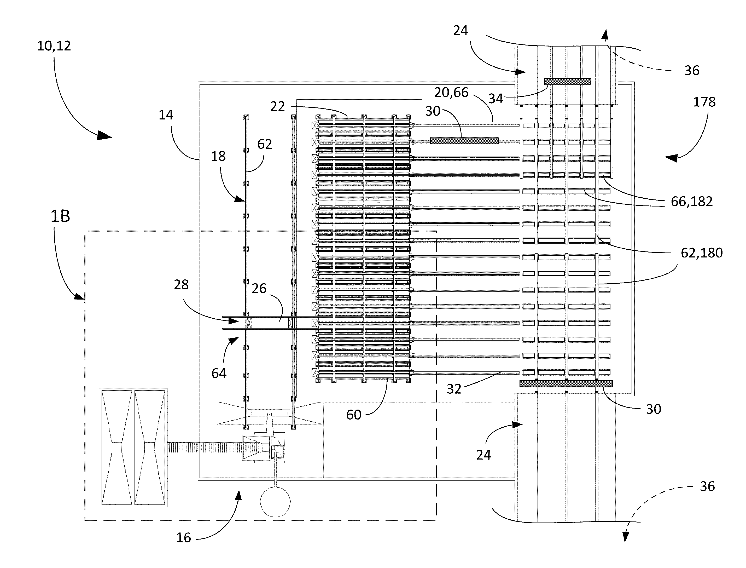
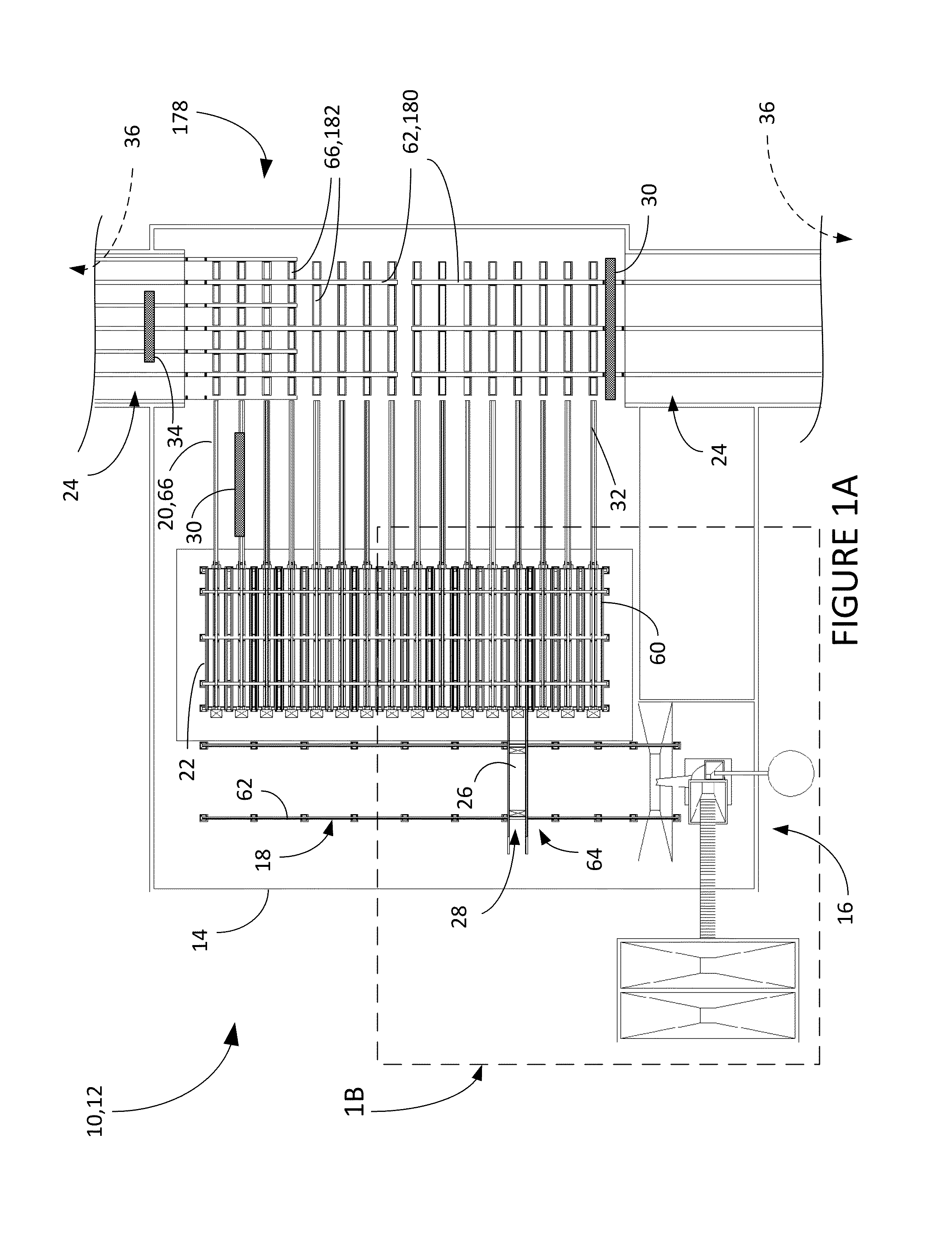
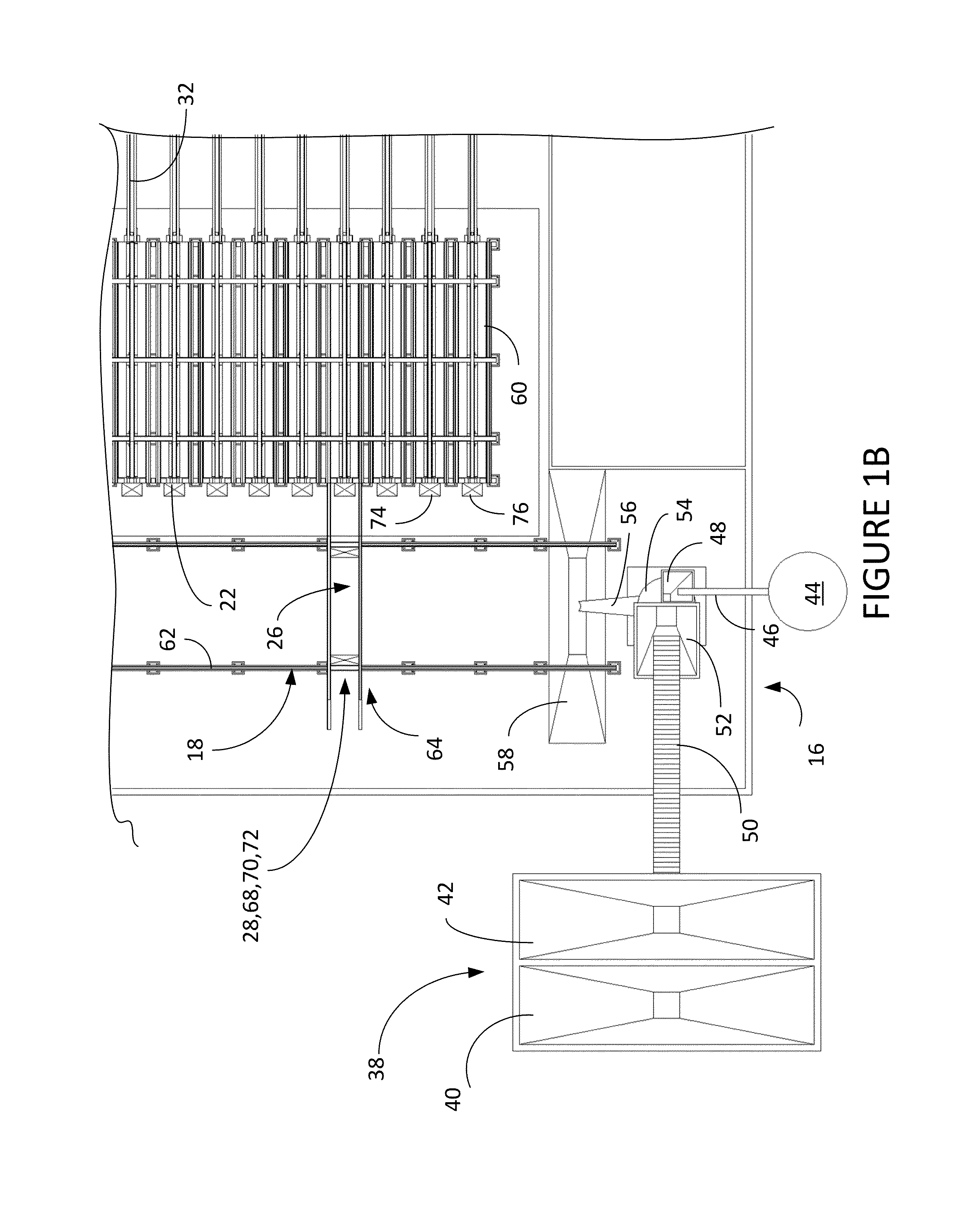
[0048]the present invention is a device, method and system for manufacture of precast concrete structural members. An overhead plan view of the preferred embodiment is the fabrication system illustrated in FIGS. 1A and B and the other figures of the drawings and is designated by the general reference character 10. The system of the present invention 10 provides an automated system for the fabrication of precast modular blocks for building construction, which is highly efficient and allows the production of much greater numbers of precast modular blocks of a larger size then is possible by use of prior casting equipment and methods.

[0049]The purpose of the fabrication system 10 is to create precast block units of the type illustrated in FIG. 2. The typical precast block unit shown in perspective view in FIG. 2 is designated by the reference number 1. As shown, the block unit 1 is laterally symmetrical and includes a first sidewall 2 and a second sidewall 3, situated on either side of...

embodiment 10

[0057]As illustrated in FIGS. 1A and B and the subsequent illustrations, it may be seen that the overall modular fabrication system 10 for precast block units 1 includes general components which recur modularly. Among those illustrated are a casting machine #174, a casting machine #276 and so on for as many repetitions as are needed in the overall system. In the preferred embodiment 10 illustrated in FIGS. 1A and B, there are sixteen casting machines shown, with only the first two being provided with reference numbers.

[0058]The details of a representative one of the casting machines 22 is shown in FIGS. 3-6. The casting machine 22 is shown in perspective views in FIGS. 3-4 in first open configuration 78 and then closed configuration 80. Details of the perspective view of the left end of the casting machine 22 are shown in FIGS. 5-6. Additionally, the stages in the operating cycle of the casting machine are shown in a series of cross-sectional views taken initially from line 7-7 of F...

second embodiment

[0140]A second embodiment which is presently most preferred is a device, method and system for manufacture of precast concrete structural members which includes many new features. The original element numbering has been retained where the original elements are substantially unchanged. Where existing elements have been modified, but perform substantially the same function, the element number has had 700 added to the original number, so that for example “block transport system 20” is now “block transport system 720”. Where new elements are included which were not present in the original embodiment, the element numbers are all numbered starting with “900”. Drawings for the new embodiment are added to the original drawings starting at new FIG. 31. An overhead plan view of the second preferred embodiment is the fabrication system illustrated in FIGS. 31-32 and is designated by the general reference character 710. The system of the present invention 710 provides an automated system for th...


PUM

PropertyMeasurementUnit
fillet radiusaaaaaaaaaa
angleaaaaaaaaaa
angleaaaaaaaaaa

Abstract

A concrete delivery subsystem for delivering concrete to a plurality of casting machines having a concrete mixing source, a concrete pump; and a concrete transfer system, which includes a concrete placement boom a concrete delivery hose, and a concrete manifold having a splitting edge having a fillet radius within the range of 0.005 inch. to 0.01 inch. Also a concrete manifold having a splitting edge having a fillet radius within the range of 0.005 inch. to 0.01 inch.

Description

[0001]The present application is a continuation-in-part of pending application Ser. Nos. 14 / 724,812 and 14 / 724,816 filed May 29, 2015 and Ser. No. 12 / 957,700 filed Dec. 1, 2010 by the same inventors.TECHNICAL FIELD[0002]The present invention relates generally to the field of construction, and more particularly to apparatus for manufacturing precast blocks for the construction of walls and other structures.BACKGROUND ART[0003]Precast concrete structural members are becoming increasingly known and used to create buildings or other structures. These precast structural members include blocks, foundation elements and partial wall units and incorporate a wide range of precast block designs that vary from the simple to the very complex. The most elementary precast block designs are those used in basic, concrete masonry, such as the well-known “cinder block”. While concrete masonry units (CMUs) may be designed for a variety of applications, they can result in structures that are structurall...

Claims


Application Information

Patent Timeline
Patent Type & Authority Patents(United States)
IPC IPC(8): B28B13/02B28B1/14B28C1/00
CPCB28B7/0044B28B7/10B28B7/183B28B7/22B28B7/285B28B13/026B28B15/00E04C1/00E04C2/04B28B13/028B28B1/14B28B13/021B28C1/003
Inventor GARFINKEL, ERIKMACMILLAN, JOHN R.
Owner SPEEDBLOCK INC
Why Eureka
Try Eureka