
Desiccant container structure

a container and desiccant technology, applied in the field of containers, can solve the problems of ineffective test strips, children are easily to get desiccants, and ineffective test strips, and achieve the effect of more space for accommodation spa

Inactive Publication Date: 2015-10-15
CHEN ERIK
View PDF0 Cites 15 Cited by
  • Summary
  • Abstract
  • Description
  • Claims
  • Application Information

AI Technical Summary

Benefits of technology

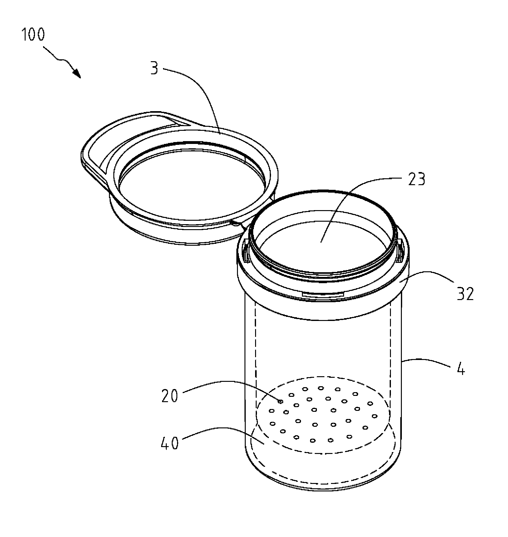
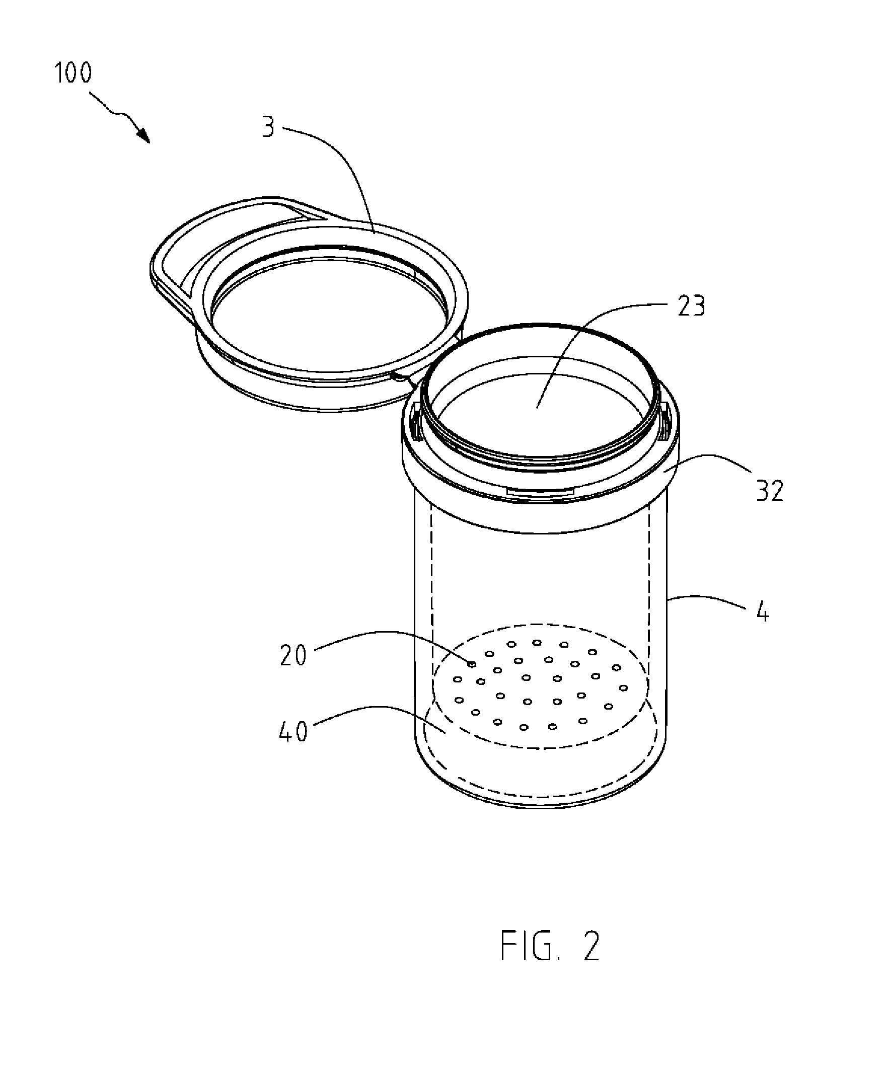
The present invention provides a desiccant container structure that can separate and store objects and desiccant to prevent moisture from affecting the objects. The structure allows users to easily identify the state of the desiccant outside the container. The desiccant absorbs moisture from the accommodation space through multiple holes, and the state of the desiccant can be viewed through a transparent portion. This separation of the objects and desiccant makes more space in the container and prevents children from accessing the desiccant. Users can replace the desiccant when its appearance or color is abnormal, and consumers are aware that the objects stored in the desiccant container structure are affected by moisture.

Problems solved by technology

However, even though the container body 1 can be sealed by the cover 11, the accommodation space 10 still remains air therein where moisture and dust will affect the nature of the test strip and render the test strip ineffective.
However, the desiccants placed directly in the accommodation space 10 not only occupy the limited space of the container body 1 for storing objects or test strips, but also arise a safety problem that children are easily to get the desiccants in the container body 1 and to eat mistakenly.
Besides, the cover 11 tends to be deformed after used for a period of time and forms gaps with the container body 1, whereas outside air leaks in the accommodation space 10 and renders the test strip ineffective.
On the other hand, because the desiccants are placed inside the container body 1, users have to open the cover 11 to identify the state of the desiccant, such as color or change of the appearance, but each time of the opening of the cover 11 will let the moisture from outside go in and thus seriously affect the lifespan of the desiccants.

Method used


Image

  • Desiccant container structure
  • Desiccant container structure
  • Desiccant container structure

Examples


Embodiment Construction

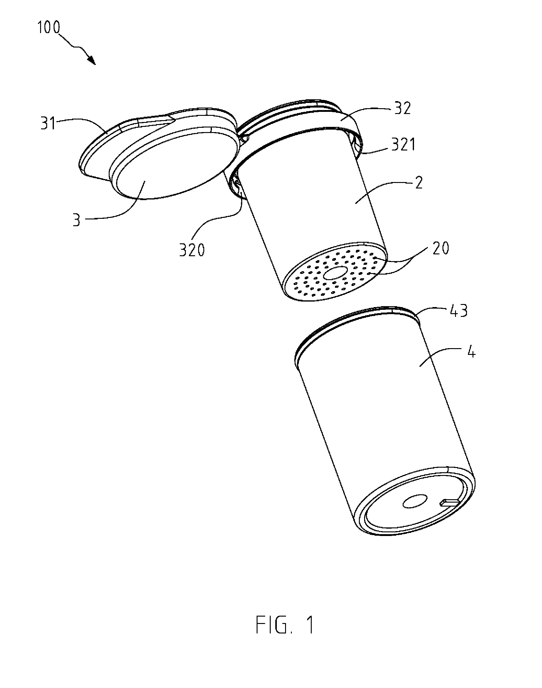
[0023]A desiccant container structure 100 of the present invention is intended to preserve objects and ensure that the objects being preserved are not affected and damaged by moisture. The objects to be preserved can be, such as, for example, test strips, electronic components, electrical instruments, or food.

[0024]Referring to FIGS. 1 and 2 showing a preferable embodiment of the present invention, the desiccant container structure 100 comprises a main body 2, a lid 3 and a desiccant storing element 4. The main body 2 forms an accommodation space 23 therein, with one end of the main body 2 open widely, for accommodating at least one object, such as a test strip 6 in this embodiment. The main body 2 has a side portion formed with a plurality of through holes 20, wherein the side portion of the main body 2 corresponds to a bottom of the main body 2, but is not limited thereby.

[0025]The lid 3 is removably connected to one end of the main body 2 and is capable of covering the accommodat...


PUM


Abstract

A desiccant container structure includes a main body, a lid, and a desiccant storing element having at least a viewing portion made of a transparent material. The main body is formed with a plurality of through holes and an accommodation space for accommodating an object. The desiccant storing element is formed with a storing chamber for accommodating a desiccant and communicating with the main body through the plurality of through holes. The desiccant in the desiccant storing element is capable of absorbing moisture from the accommodation space through the plurality of through holes for maintaining the object in a dry state, and a state of the desiccant is capable of being viewed directly through the transparent viewing portion.

Description

BACKGROUND OF THE INVENTION[0001]1. Field of the Invention[0002]The present invention relates to a container, and more particularly to a desiccant container structure capable of providing high moisture-proof effect.[0003]2. Related Art[0004]Referring to FIG. 9 showing a conventional container for storing a test strip, the conventional container includes a container body 1 forming an accommodation space 10 therein, and a cover 11. The test strip is preserved in the accommodation space 10 which is sealed by covering the cover 11 onto the container body 1 for preventing from being affected by moisture and causing ineffectiveness of the test strip. However, even though the container body 1 can be sealed by the cover 11, the accommodation space 10 still remains air therein where moisture and dust will affect the nature of the test strip and render the test strip ineffective. As a result, in order to keep the test strip in a dry state, a traditional way is to provide desiccants in the acc...

Claims


Application Information

Patent Timeline
Patent Type & Authority Applications(United States)
IPC IPC(8): B65D81/26B65D43/14B65D25/54
CPCB65D81/268B65D2543/00435B65D43/14B65D25/54B65D51/244B65D81/266
Inventor CHEN, ERIK
Owner CHEN ERIK
Learn More