Discharging device

a discharging device and dispensing device technology, applied in liquid transfer devices, volume meters, instruments, etc., can solve the problems of only having a particularly small loss volume, only having a complex and expensive manufacturing process, and not being able to rotate into the closed position. , to achieve the effect of simple and inexpensive manufactur

Inactive Publication Date: 2015-10-15
SULZER MIXPAC AG
View PDF5 Cites 5 Cited by
  • Summary
  • Abstract
  • Description
  • Claims
  • Application Information

AI Technical Summary

Benefits of technology

[0007]In light of this, it is the object of the invention to propose a dispensing apparatus which can be manufactured simply

Problems solved by technology

Such closure plugs are only complex and thus expensive in manufacture.
Furthermore, the dispensing apparatus only has a particularly small loss volume.
In addition, a security against turning back can be provided so that a rotation into the closed position is no longer possible after adjusting the dispensing position.
It is thus not poss

Method used


Image

  • Discharging device
  • Discharging device
  • Discharging device

Examples


Embodiment Construction

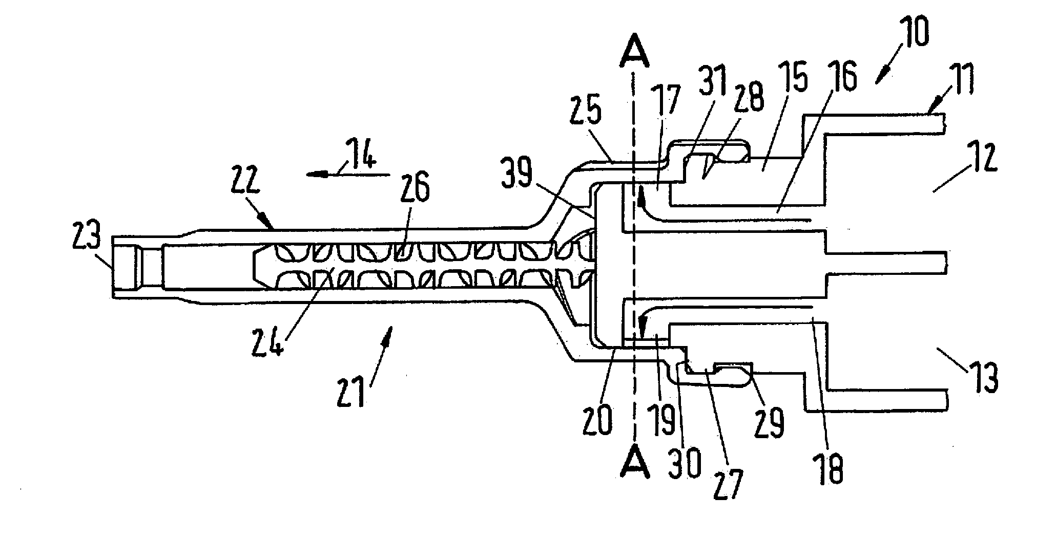
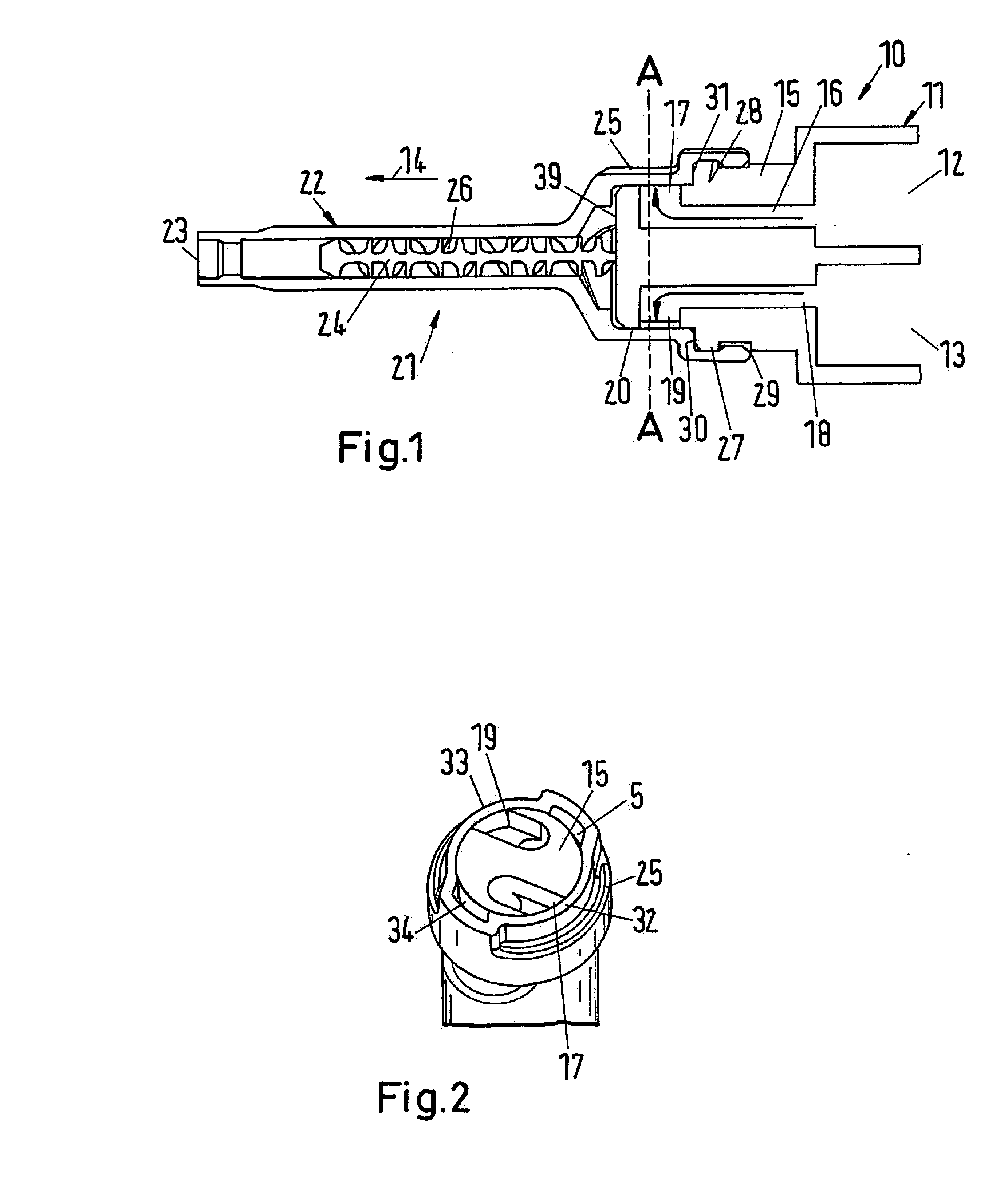
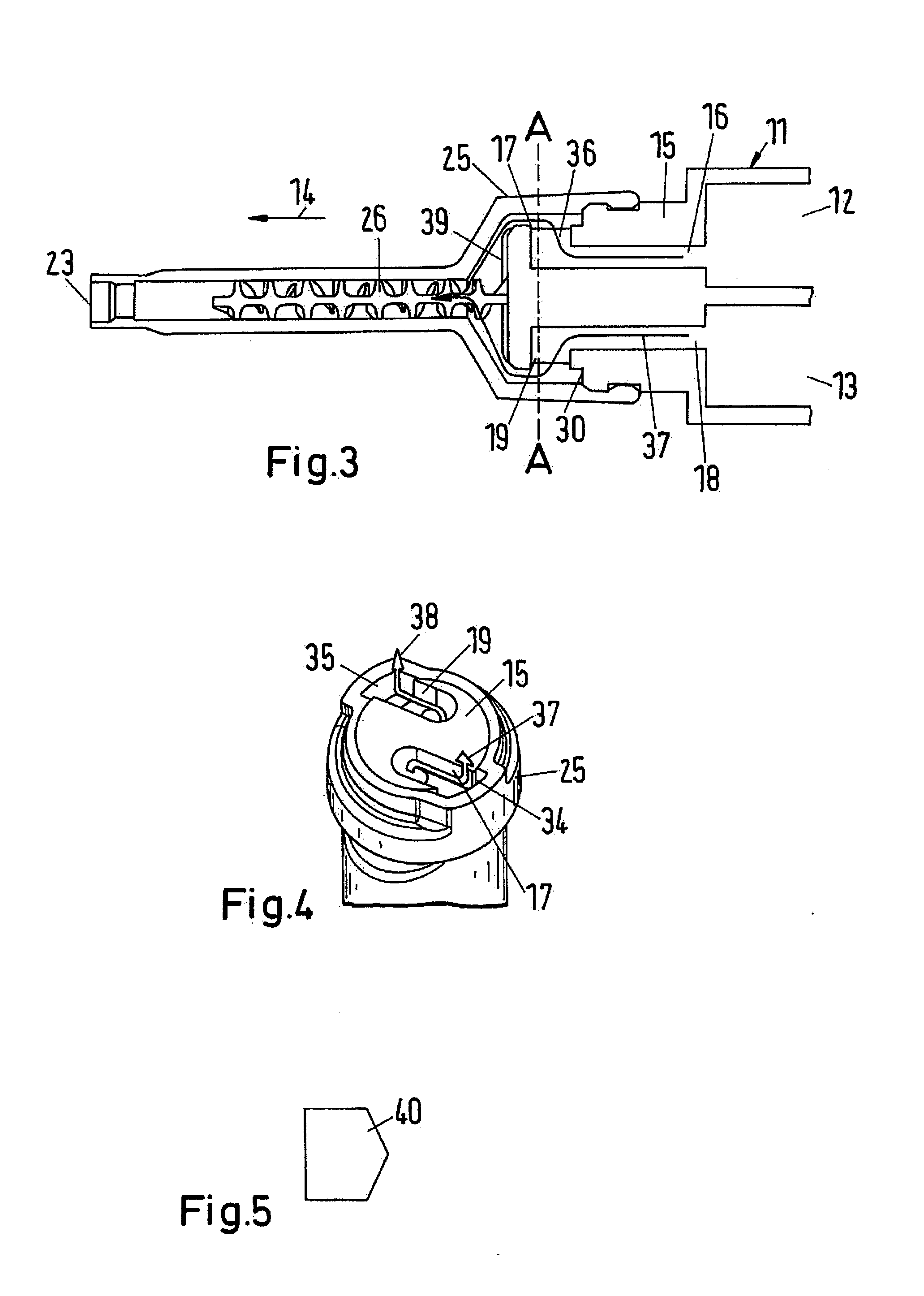
[0041]In accordance with FIG. 1, a dispensing apparatus 10 has a storage container 11 for two flowable components. The storage container 11 has a first storage chamber 12 for a first component and a second storage chamber 13 for a second component, with the storage chambers 12, 13 only being shown in part. The storage chambers 12, 13 have a hollow cylindrical inner contour and are arranged in parallel to one another and in parallel to a dispensing direction 14. The storage container 11 has an outlet flange 15 which bounds the two storage chambers 12, 13 in the dispensing direction 14 and has a first connection passage 16 from the first storage chamber 12 to a first component outlet 17 and has a second connection passage 18 from the second storage chamber 13 to a second component outlet 19. A respective piston, not shown, which is displaceable in the dispensing direction 14 and by means of which the two components can be urged out of the storage chambers 12, 13 to their respective co...


PUM


Abstract

A dispensing apparatus includes a storage container having an outlet flange with a component outlet which is at least partly surrounded by an inlet flange. The inlet flange is configured to adopt a closed position and a dispensing position with respect to the outlet flange. A change from the closed position into the dispensing position is carried out by a rotation of the inlet flange with respect to the outlet flange. The component outlet is arranged at a cylindrical jacket surface of the outlet flange. The first component outlet is closed by the inlet flange in the closed position of the inlet flange. In the dispensing position, a connection is established by a crossover passage between the first component outlet and a dispensing opening.

Description

CROSS-REFERENCE TO RELATED APPLICATIONS[0001]This application is a U.S. National stage application of International Application No. PCT / EP2013 / 067325, filed Aug. 20, 2013, which claims priority to EP Application 12189500.7 filed on Oct. 23, 2012, the contents of each of which are hereby incorporated herein by reference.BACKGROUND[0002]1. Field of the Invention[0003]The invention relates to a dispensing apparatus for a flowable component.[0004]2. Background Information[0005]A dispensing device for two flowable components is described in EP 1 968 751 B1. The dispensing device has a storage container having a first storage chamber for a first component and having a first component outlet and has a dispensing element which is connected to the storage container and has a dispensing opening. The storage container additionally has a second storage chamber for a second component and has a second component outlet. The dispensing apparatus is designed as a static mixer in which the two compon...

Claims


Application Information

Patent Timeline
IPC IPC(8): B65D81/32B05C17/01B05C17/005
CPCB65D81/325B65D81/3255B05C17/0116B05C17/00576B05C17/00506B05C17/00553
Inventor LEUE, PERCY
Owner SULZER MIXPAC AG
Why Eureka
Try Eureka