Method for producing a flow rich in methane and a flow rich in c2+ hydrocarbons, and associated installation

a technology of methane and hydrocarbons, which is applied in the direction of lighting and heating apparatus, liquid storage, solidification, etc., can solve the problems of further increase in the efficiency of the method, and achieve the effect of occupying little space and being economical and efficien

Active Publication Date: 2015-10-15
TECH FRANCE SA
View PDF0 Cites 2 Cited by
  • Summary
  • Abstract
  • Description
  • Claims
  • Application Information

AI Technical Summary

Benefits of technology

[0027]Therefore, an object of the invention is to obtain a production method which allows separation of a supply flow containing hydrocarbons into a flow rich in C2+ hydrocarbons and a flow rich in methane, in a very economical and very efficient manner, taking up little space.

Problems solved by technology

However, economic constraints require a further increase in the efficiency of the method whilst retaining a very high level of efficiency of ethane extraction.

Method used


Image

  • Method for producing a flow rich in methane and a flow rich in c2+ hydrocarbons, and associated installation
  • Method for producing a flow rich in methane and a flow rich in c2+ hydrocarbons, and associated installation
  • Method for producing a flow rich in methane and a flow rich in c2+ hydrocarbons, and associated installation

Examples


Embodiment Construction

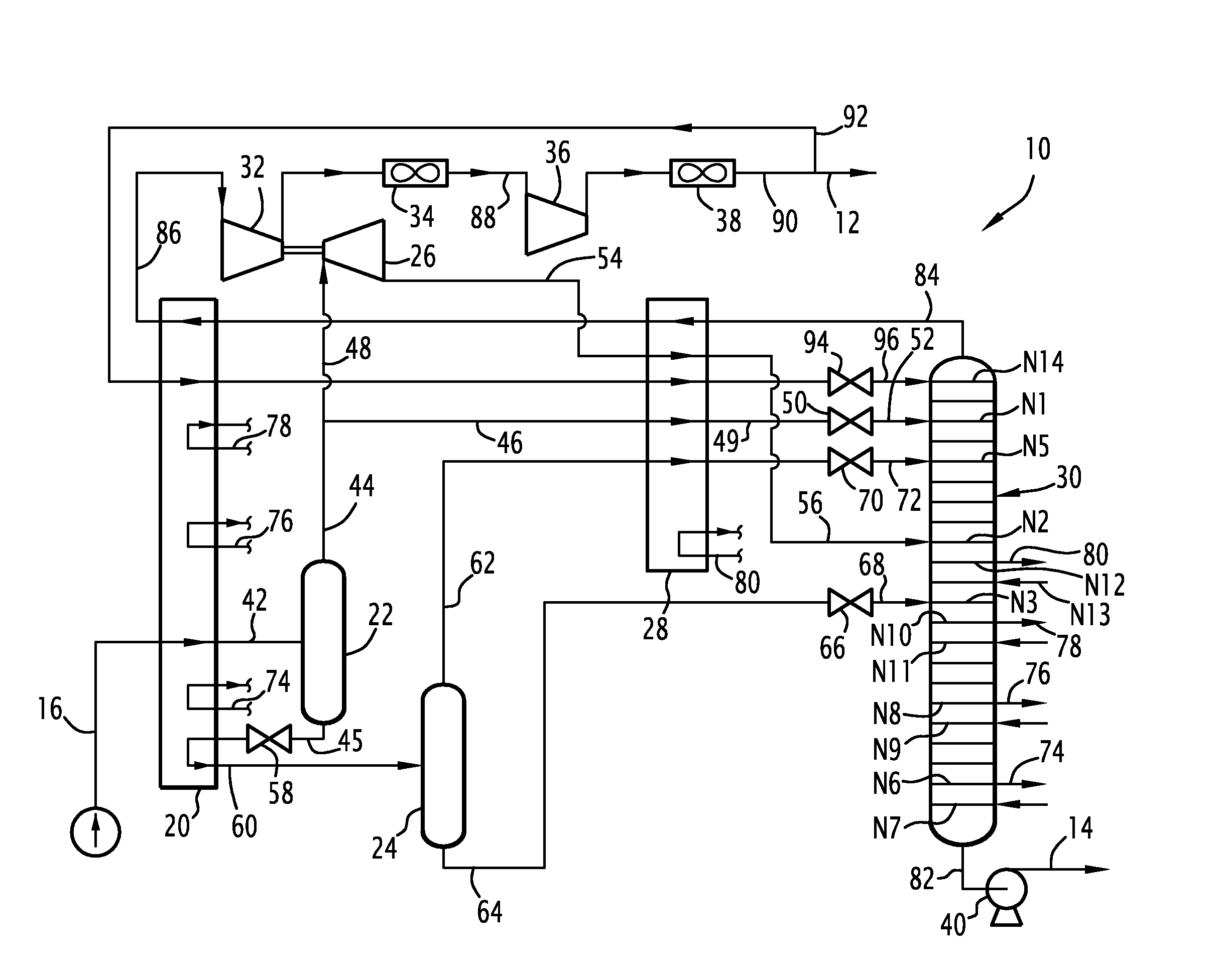
[0095]Hereinafter, a flow flowing in a conduit and the conduit which transports it will be referred to using the same reference numerals.

[0096]Furthermore, unless otherwise indicated, the percentages set out are molar percentages and the pressures are given in bar absolute. The efficiency level of each compressor is selected to be 82% polytropic and the efficiency level of each turbine is 85% adiabatic. Similarly, the distillation columns described use plates but they can also use loose or structured lining. A combination of plates and lining is also possible. The additional turbines described drive compressors but they can also drive electrical generators having variable frequency whose electricity produced may be used in the network by means of a frequency converter. The flows whose temperature is above ambient are described as being cooled by air coolers. In a variant, it is possible to use water exchangers, for example, with fresh water or sea water.

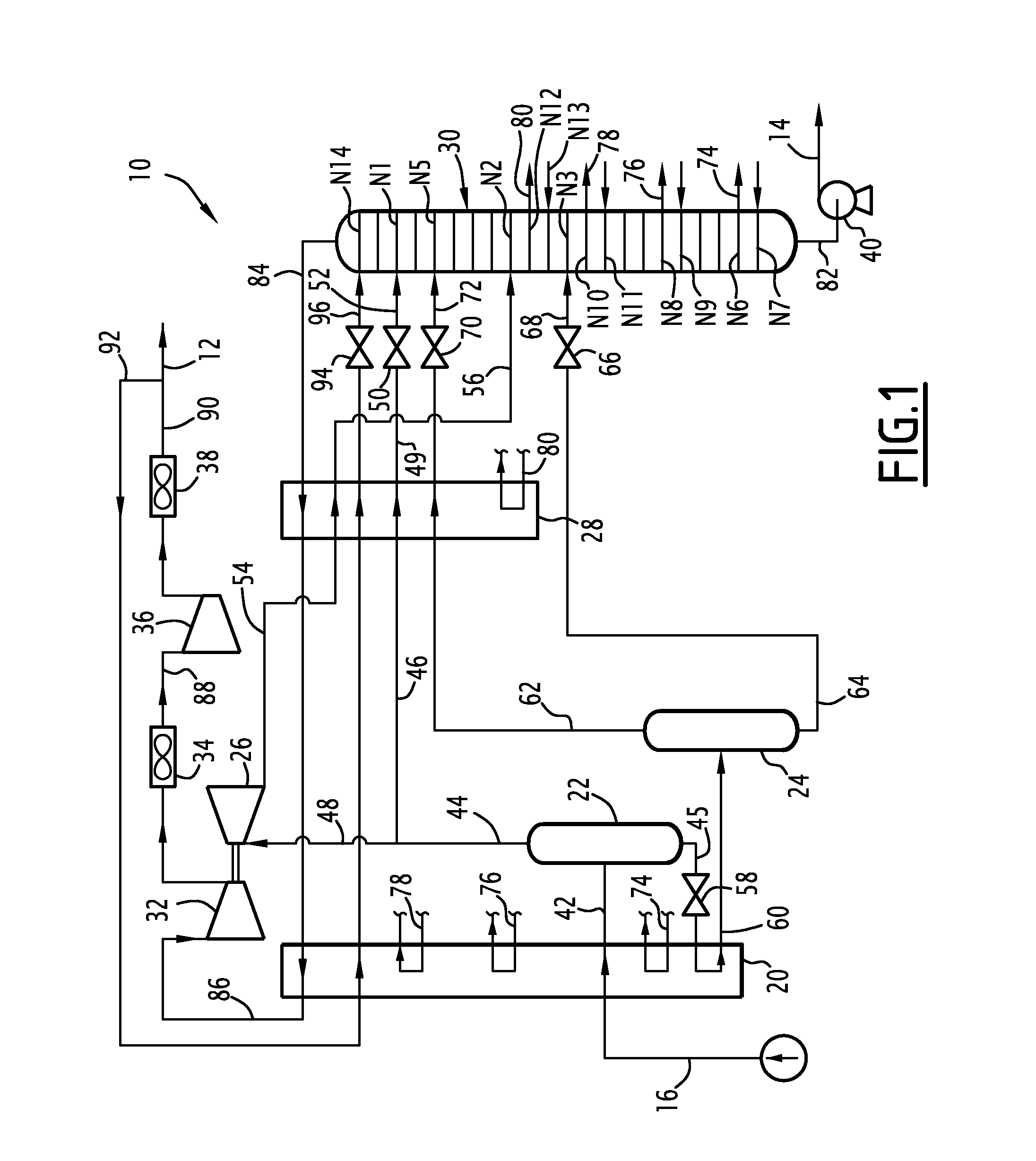
[0097]FIG. 1 illustrates a fi...


PUM


Abstract

This method envisions cooling the supply flow in a first heat exchanger, separation in a first separation flask in order to produce a light upper flow and a heavy lower flow and dividing the light upper flow into a supply fraction of a dynamic pressure reduction turbine and a supply fraction of a first distillation column. A cooled reflux flow is formed from an effluent from a dynamic pressure reduction turbine, the portion of the effluent being cooled and at least partially liquefied in a heat exchanger. The cooled reflux flow is introduced from the heat exchanger into the first distillation column.

Description

CROSS REFERENCE TO RELATED APPLICATIONS[0001]The present application is a divisional of U.S. patent application Ser. No. 12 / 831,362, filed Jul. 7, 2010, which claims priority of French Application No. 0954781, filed Jul. 9, 2009, the entire contents of which are incorporated in full herein by reference.BACKGROUND OF THE INVENTION[0002]The present invention relates to a method for producing a flow rich in methane and a flow rich in C2+ hydrocarbons from a supply flow containing hydrocarbons, of the type comprising the following steps:[0003]cooling at least a first fraction of the supply flow in a first heat exchanger;[0004]introducing the first cooled supply fraction into a first separation flask in order to produce a light upper flow and a heavy lower flow;[0005]dividing the light upper flow into a turbine supply fraction and a column supply fraction;[0006]pressure reduction of the turbine supply fraction in a first dynamic pressure reduction turbine and introduction of at least a p...

Claims


Application Information

Patent Timeline
Patent Type & Authority Applications(United States)
IPC IPC(8): F25J3/02
CPCF25J3/0209F25J3/0233F25J3/0238F25J2200/02F25J2200/30F25J2200/50F25J2200/76F25J2205/04F25J2210/06F25J2230/24F25J2230/60F25J2240/02F25J2245/02F25J2270/02F25J2270/04F25J2270/06F25J2270/88F25J2290/80
Inventor GAHIER, VANESSAGOURIOU, JULIEBARTHE, LOICTHIEBAULT, SANDRA
Owner TECH FRANCE SA
Why Eureka
Try Eureka