Proximity sensing systems and methods

Active Publication Date: 2015-10-15
SZ DJI TECH CO LTD
View PDF2 Cites 26 Cited by
  • Summary
  • Abstract
  • Description
  • Claims
  • Application Information

AI Technical Summary

Benefits of technology

[0005]The present invention provides methods and systems for reducing or even eliminating the blind zone, thereby decreasing the minimum measuring distance, without increasing the production cost. Unlike the software approach mentioned above, the present invention makes it possi

Problems solved by technology

Traditionally, the application of the ultrasonic sensors is limited by the existence of the blind zone, which is caused by residual mechanical vibration of the ultrasonic transducer.
However, the software approach merely avoids but does not reduce or remove the blind zone.
That i

Method used


Image

  • Proximity sensing systems and methods
  • Proximity sensing systems and methods
  • Proximity sensing systems and methods

Examples


Example

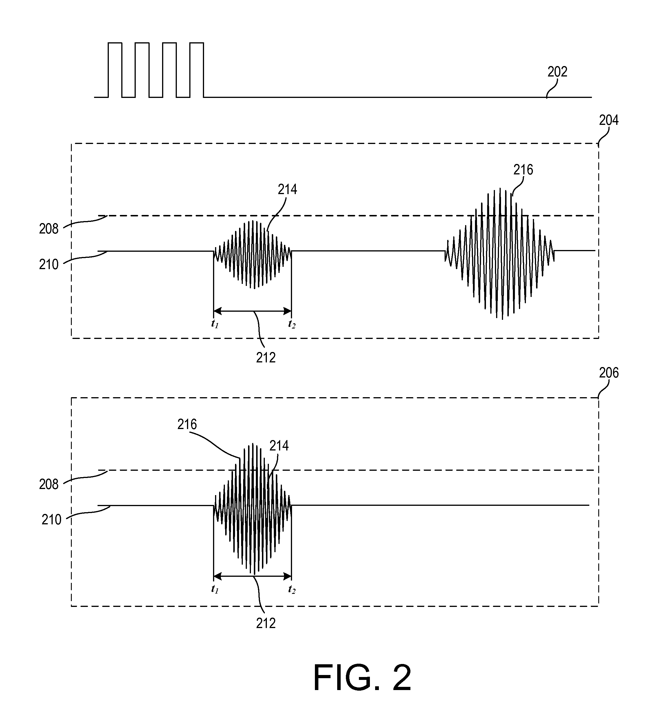
[0053]Methods, systems and device are provided for reducing or eliminating a blind zone associated with ultrasonic sensors, thereby decreasing the minimum measuring distance, without reducing the maximum measuring distance and without increasing production cost. According to an aspect of the present invention, methods and systems for reducing or eliminating blind zone associated with ultrasonic sensing are provided. In some embodiments, an attenuator circuit is introduced to attenuate the received signals during the time period corresponding to the blind zone in order to remove substantially all reverberation signals while preserving substantially all echo signals as reflected from objects. The selection and de-selection of the attenuator circuit may be achieved by a controllable switch. The amount of attenuation provided by the attenuator circuit may be configurable based on values (e.g., amplitude) of actually measured reverberation signals and echo signals, among other factors.

[0...


PUM


Abstract

Methods, systems and device are provided for improving the range and accuracy of proximity measurement such as in ultrasonic sensing systems. In particular, the blind zone caused by reverberation signals can be reduced or eliminated by attenuating signals received during the time period corresponding to the blind zone without. In an implementation, an attenuator circuit is selected by a switch to process received signals during the blind zone time period and deselected by the switch after the time zone time period. Additionally, the accuracy and range of the measurement can be improved by varying the gain provided to the received signals based on the varying measuring distance. In an implementation, a gain-adjustable amplifier is controlled by a gain control signal to provide incremental gain as time increases.

Description

CROSS-REFERENCE[0001]This application is a continuation application of International Application No. PCT / CN2014 / 075192, filed on Apr. 11, 2014, the content of which is hereby incorporated by reference in its entirety.BACKGROUND OF THE INVENTION[0002]Proximity sensors such as ultrasonic sensors have been widely used to detect distance to objects. In particular, ultrasonic sensors are typically configured to generate ultrasonic signals with an ultrasonic transducer and to receive the echo signals reflected back by the objects. By calculating the time interval between sending the ultrasonic signal and receiving the echo signal, the distance to an object can be determined based on the propagation speed of sound through the propagation medium such as air.[0003]Traditionally, the application of the ultrasonic sensors is limited by the existence of the blind zone, which is caused by residual mechanical vibration of the ultrasonic transducer. Ultrasonic transducers are typically configured ...

Claims


Application Information

Patent Timeline
IPC IPC(8): G01B17/00G01S15/93G01S15/931
CPCG01S7/529G01S7/5273G01B17/00G01S15/93G01S15/931G01S15/10G01S15/101G01S7/524G01S7/527
Inventor ZHOU, WANCHENGHUANG, LIMING
Owner SZ DJI TECH CO LTD
Why Eureka
Try Eureka