Mirror for checking blind spot

a mirror and blind spot technology, applied in the direction of mirrors, mountings, instruments, etc., can solve the problems of low eye level, interference with traffic, and inclination to miss the mirror, so as to facilitate recognition of the image, improve safety, and facilitate grasping

Inactive Publication Date: 2015-10-15
KOMY
View PDF7 Cites 0 Cited by
  • Summary
  • Abstract
  • Description
  • Claims
  • Application Information

AI Technical Summary

Benefits of technology

[0007]In the mirror for checking a blind spot of the present invention, since the sheet in which the many strip reflective surfaces are arranged parallel and adjacent to one another is bendable in a cylindrical shape about the axis parallel to the direction transverse to the extension direction of the strip reflective surfaces, the mirror can be attached while being bent along the curved surface to which the mirror is attached. Accordingly, the mirror does not interfere with traffic.
[0008]Moreover, since the inclination angle formed by the width direction of each of the strip reflective surfaces and the surface direction of the sheet is sequentially changed with an increase in the distance in the direction transverse to the extension direction of the strip reflective surfaces and the aggregate of the strip reflective surfaces has the cylindrical convex mirror function, an image of a wide angle can be obtained through the aforementioned convex mirror function, only in the direction transverse to the extension direction of the strip reflective surfaces.
[0009]Meanwhile, when the sheet is attached to the curved surface with the extension direction of the strip reflective surfaces being aligned with the circumferential direction of the curved surface of the structure, an image of a wide angle can be obtained in the extension direction of the strip reflection surfaces through a convex mirror function obtained by aligning the extension direction of the strip reflective surfaces with the curved surface of the structure. Since feeling of strangeness in the aspect ratio of the image is reduced by the convex mirror functions respectively in the direction transverse to the extension direction of the strip reflective surfaces and the extension direction, recognition of the image can be facilitated. A situation in the blind spot is thereby made easier to grasp and this is effective in improving the safety.

Problems solved by technology

Accordingly, the convex mirror has a problem that people with low eye levels such as short people and people on wheelchairs tend to miss the mirror.
However, in a case where the Fresnel mirror is attached to a curved surface of a column or the like, the entire surface of the planar Fresnel mirror is not attached to the curved surface but most of the surface of the Fresnel mirror is spaced away from the curved surface, and this spaced-away portion interferes with traffic.
However, since the conventional Fresnel mirror has a spherical convex mirror function, this convex mirror function is further increased and an image is distorted to be greatly stretched in a circumferential direction of the curved surface, when the mirror is bent along the curved surface.
In other words, the conventional Fresnel mirror has a problem that the aspect ratio of the image greatly deviates from 1:1 and recognition of the image becomes difficult.

Method used


Image

  • Mirror for checking blind spot
  • Mirror for checking blind spot
  • Mirror for checking blind spot

Examples


Embodiment Construction

[0021]A mirror for checking a blind spot of the present invention is described below based on embodiments shown in the drawings.

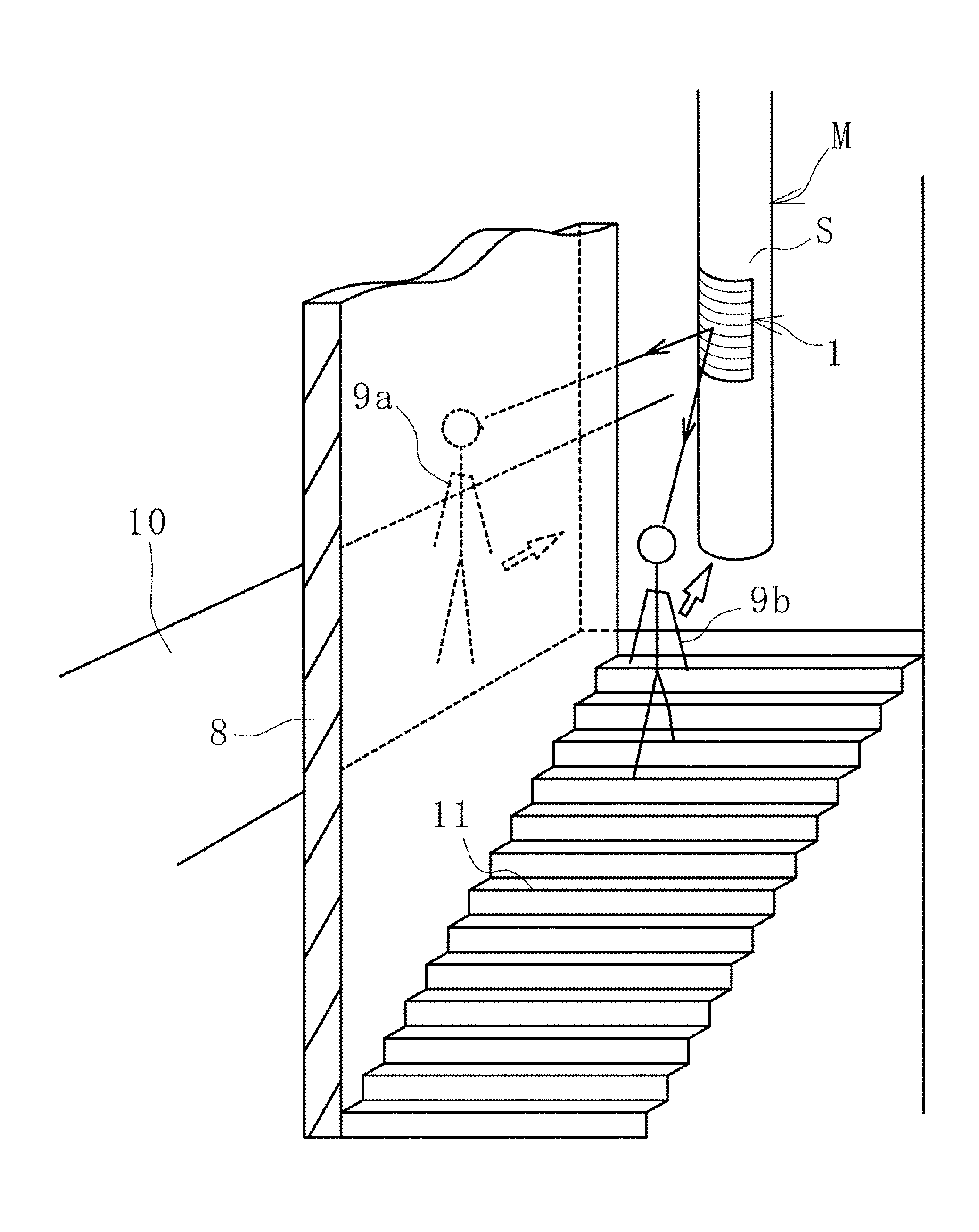
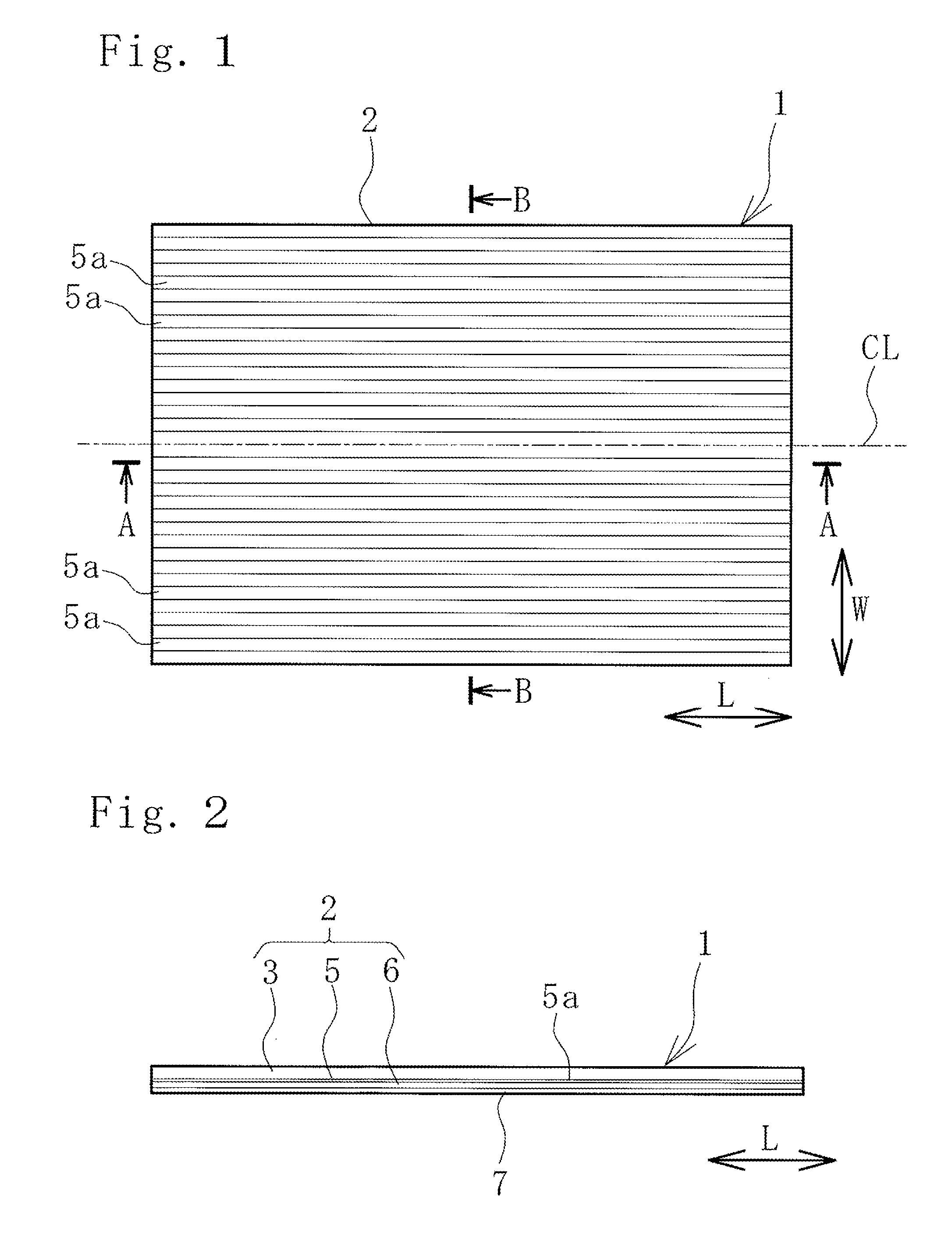
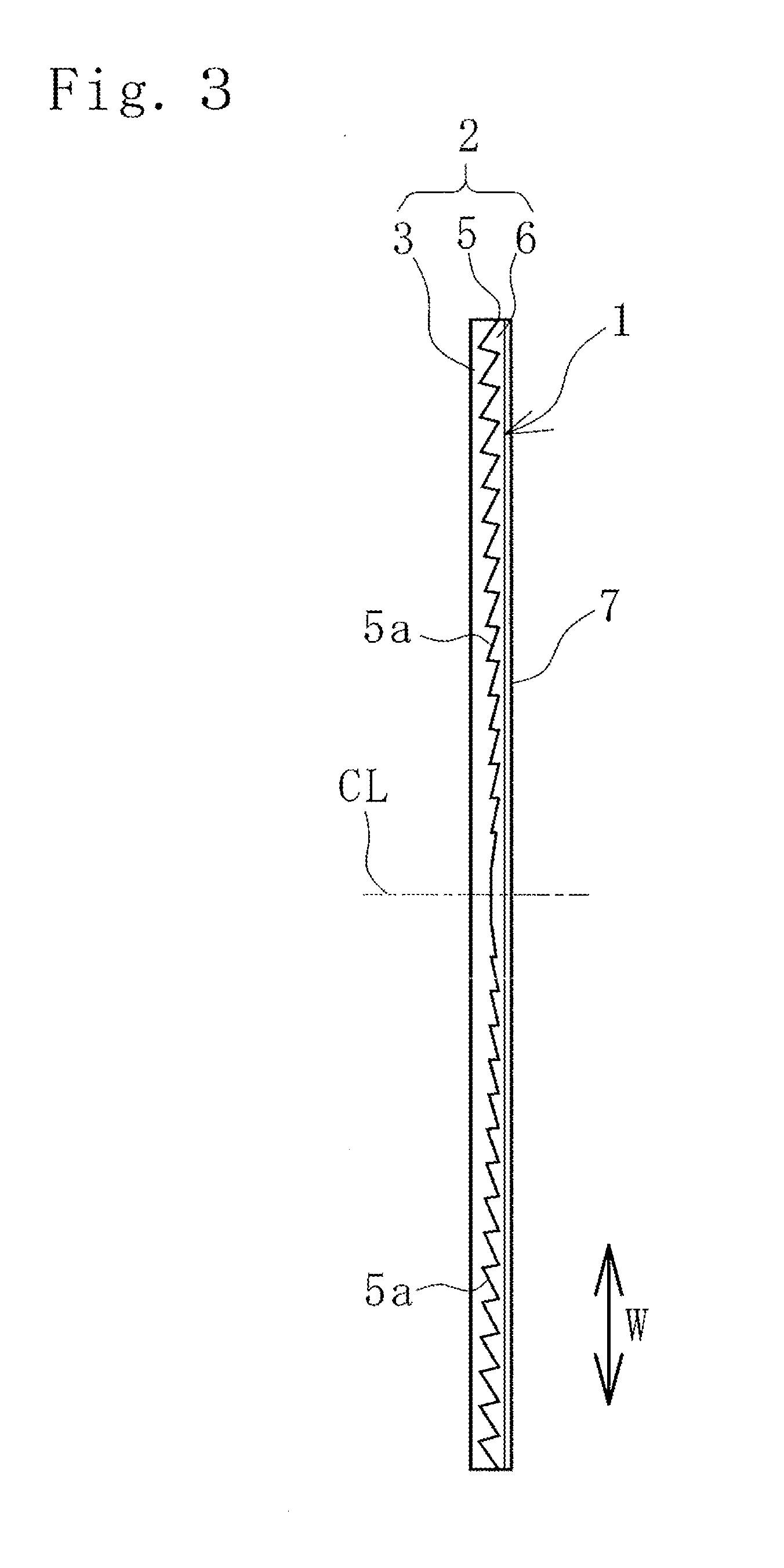
[0022]As illustrated in FIGS. 1 to 4, a mirror 1 for checking a blind spot (hereafter, referred to as mirror 1) of the present invention includes a sheet 2 formed by laminating a transparent resin plate 3, a reflective layer 5, and a coating layer 6 to one another. An attachment member 7 for attaching the mirror 1 to a curved surface S of a structure M is provided on a back surface of the sheet 2. Adhering means such as a double-sided adhesive tape and adhesive can be given as examples of the attachment member 7. Screws may be used instead of such adhering means. Alternatively, the adhering means and the screws can be used together. In a case where the attachment member 7 is the adhering means, the adhering means may be provided over the entire back surface of the sheet 2 or only in a periphery thereof. In the case of the screws, the sheet 2 may be screwed ...


PUM


Abstract

A mirror, when attached along a curved surface, facilitates recognition of an image in a blind spot by reducing a feeling of strangeness caused by the aspect ratio of the image. Many linearly-extending strip reflective surfaces 5a are arranged on a surface of a sheet 2 to be parallel and adjacent to one another. An inclination angle A formed between a width direction of each of the strip reflective surfaces 5a and a surface direction of the sheet 2 is sequentially changed with an increase in a distance in a direction transverse to an extension direction of the strip reflective surfaces 5a. An aggregate of the strip reflective surfaces 5a has a cylindrical convex mirror function, and the mirror 1 is bendable in a cylindrical shape about an axis parallel to the direction transverse to the extension direction of the strip reflective surfaces 5a.

Description

TECHNICAL FIELD[0001]The present invention relates to a mirror for checking a blind spot, and more specifically to a mirror for checking a blind spot which, when attached to a curved surface of a column or the like, can be attached along the curved surface and facilitate recognition of an image of a blind spot by reducing feeling of strangeness in the aspect ratio of the image as much as possible.BACKGROUND ART[0002]A convex mirror and a planar Fresnel mirror are known as mirrors for preventing collision. Since the convex mirror protrudes greatly from an attachment surface with a fitting therebetween, the convex mirror is attached at a high position so as not to interfere with traffic. Accordingly, the convex mirror has a problem that people with low eye levels such as short people and people on wheelchairs tend to miss the mirror.[0003]Since the planar Fresnel mirror is attached planarly along an attachment surface, the Fresnel mirror hardly protrudes and does not have the problem ...

Claims


Application Information

Patent Timeline
Patent Type & Authority Applications(United States)
IPC IPC(8): G02B5/10B60R1/08
CPCB60R1/081G02B5/10G02B5/09
Inventor YOKOTA, TETSUOIWATA, YOSHIYUKITAKEDA, HISANAGAKOYAMA, YOSHINORISHINOZAKI, MASAKI
Owner KOMY
Why Eureka
Try Eureka