Optical connector

Active Publication Date: 2015-10-15
OPTICIS
View PDF1 Cites 11 Cited by
  • Summary
  • Abstract
  • Description
  • Claims
  • Application Information

AI Technical Summary

Benefits of technology

[0006]The present disclosure provides an optical connector including insertion grooves, first guide-walls, and second guide-walls. Therefore, when the optical connector is assembled, optical fiber lines of an optical cable may be automatically aligned with optical devices corresponding to the optical fiber lines.
[0007]Furthermore, in the optical connector of the present disclosure, optical paths may be easily changed by varying the positions of supports, and

Problems solved by technology

However, these methods are disadvantageous because

Method used


Image

  • Optical connector
  • Optical connector
  • Optical connector

Examples


Embodiment Construction

Technical Problem

[0004]To solve the above-mentioned problems of the related art, the present disclosure provides an optical connector for easily connecting optical fiber lines to light-receiving or light-emitting devices in an assembly process.

Technical Solution

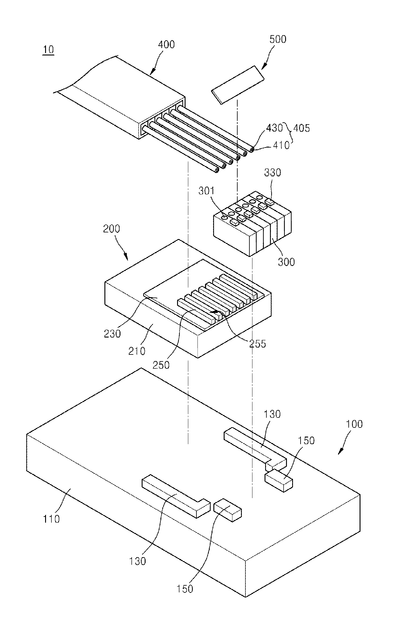
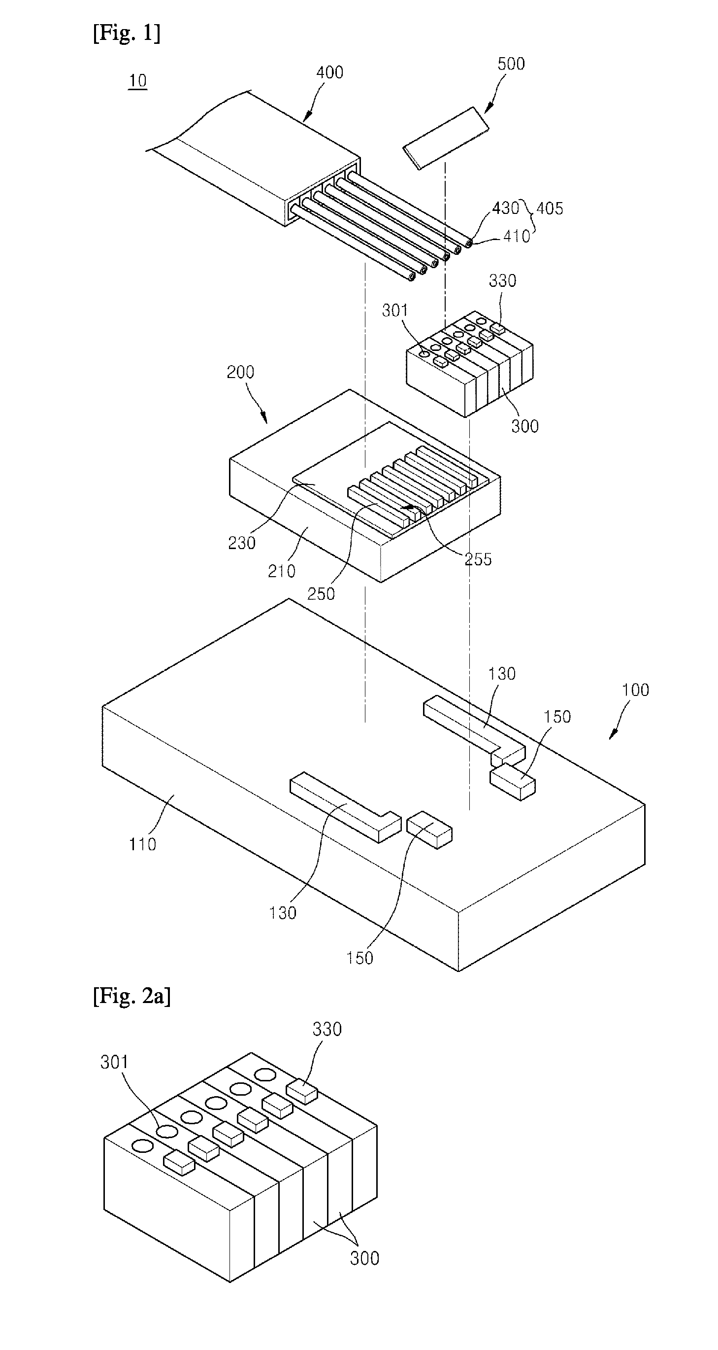
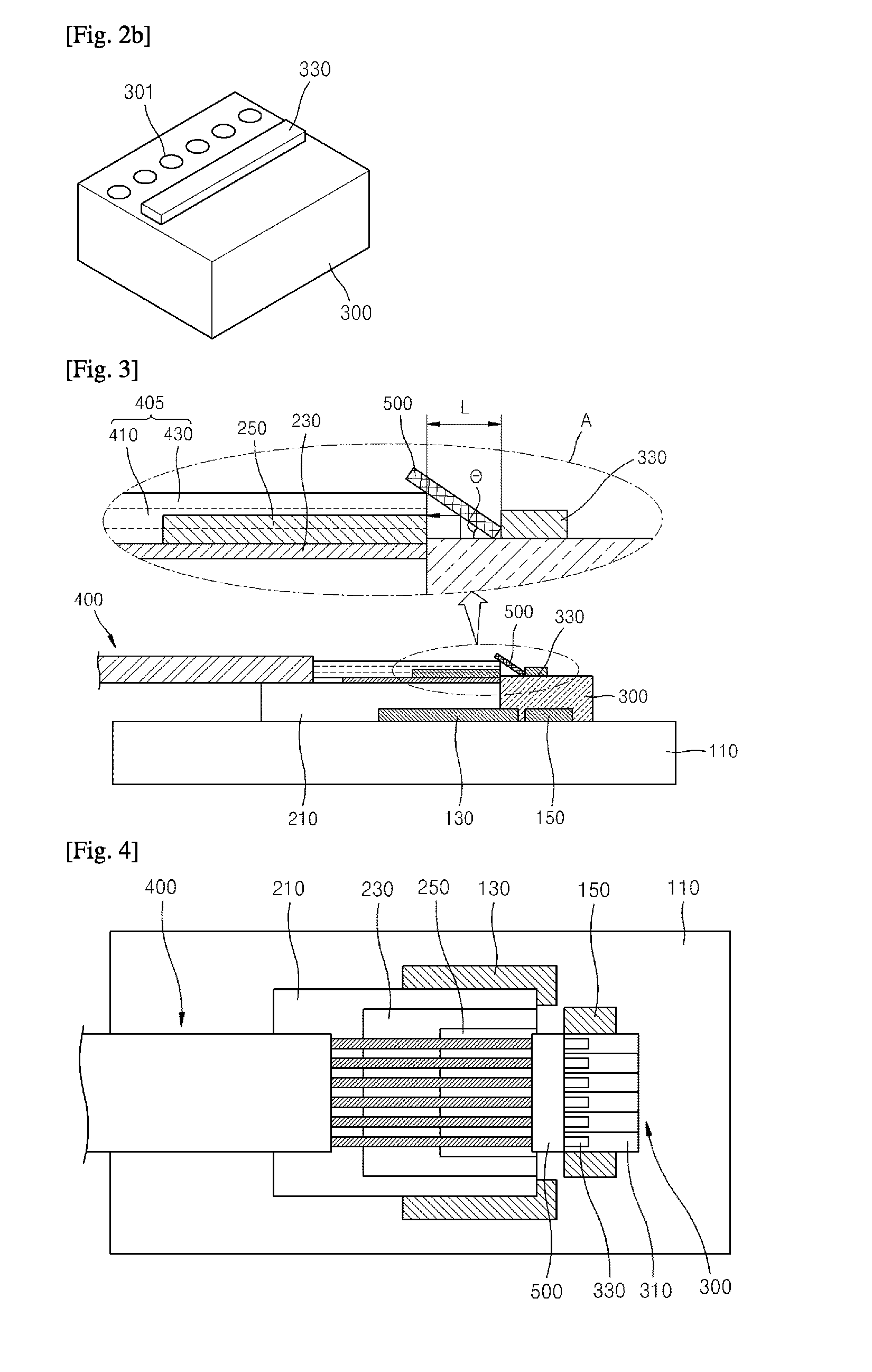
[0005]According to an embodiment of the present invention, there is provided an optical connector including: an optical fiber line fixing block including an insertion groove in which an end portion of an optical fiber line is inserted; and a submount including first guide-walls determining a position of the optical fiber line fixing block and second guide-walls determining a position of an optical device to be connected to the optical fiber line, wherein the optical fiber line fixing block and the optical device are automatically aligned by the first guide-walls and the second guide-walls.

Advantageous Effects

[0006]The present disclosure provides an optical connector including insertion grooves, first guide-walls, and second g...


PUM


Abstract

An optical connector is provided. The optical connector includes: an optical fiber line fixing block including an insertion groove in which an end portion of an optical fiber line is inserted; and a submount including first guide-walls determining a position of the optical fiber line fixing block and second guide-walls determining a position of an optical device to be connected to the optical fiber line, wherein the optical fiber line fixing block and the optical device are automatically aligned by the first guide-walls and the second guide-walls.

Description

TECHNICAL FIELD[0001]The present disclosure relates to an optical connector, and more particularly, to an optical connector for easily connecting a plurality of limit-emitting devices or a plurality of light-receiving devices to a plurality of optical fiber lines.BACKGROUND ART[0002]In general, optical connectors are used to optically transmit digital visual interface (DVI) signals or high definition multimedia interface (HDMI) signals. Optical connectors have a structure in which a device insertion member and an optical fiber insertion member are coupled to each other. A plurality of light-receiving devices or a plurality of light-emitting devices are inserted into the device insertion member. In addition, optical fiber lines are inserted into the optical fiber insertion member.[0003]Such optical connectors are required to align optical fiber lines with light ports of light-receiving or light-emitting devices for a precisely facing relationship therebetween. For this, methods such ...

Claims


Application Information

Patent Timeline
IPC IPC(8): G02B6/42G02B6/43
CPCG02B6/4292G02B6/4214G02B6/4243G02B6/4255G02B6/43G02B6/4257G02B6/4246G02B6/423G02B6/4239G02B6/4249G02B6/38G02B6/40
Inventor KIM, HEE DAELEE, HYUN SIK
Owner OPTICIS
Why Eureka
Try Eureka