
Projection welding device

Active Publication Date: 2015-10-22
HYUNDAI MOTOR CO LTD
View PDF11 Cites 0 Cited by
  • Summary
  • Abstract
  • Description
  • Claims
  • Application Information

AI Technical Summary

Benefits of technology

The present invention is a projection welding device that can rotate a shank with a welding tip, allowing the welding tip to cover a protrusion on a panel without interference from a jig. This device can prevent punching marks and ensure a high level of welding quality. The welding tip can also be rotated through a swivel unit to contact the panel through a surface contact and prevent punching marks caused by a line contact.

Problems solved by technology

However, the spot welding device forms a press mark, and there is a drawback that the press mark deteriorates external appearance quality.
Particularly, after the painting process, the press mark that is formed by a welding process is not eliminated, is exposed, and may result in deteriorated product quality.
To address this drawback, a laser brazing welding is used or a cover is used to hide the welding portion, but such methods may increase manufacturing costs.
However, in the projection welding gun device, when the rectangle type welding tip is mounted, a welding gun is to be disposed in a vertical direction on the protrusion, but the welding gun is not disposed in the vertical direction due to the interference with a jig for fixing the panel on the production site.
In this configuration, because the welding tip does not completely cover the protrusion, there is a drawback that a protruded portion is formed after the welding process.
However, in a case that a curved surface is formed on the panel, the welding tip forms a line contact with the panel, and there is a drawback that line mark is formed on the panel.

Method used


Image

  • Projection welding device
  • Projection welding device
  • Projection welding device

Examples


Embodiment Construction

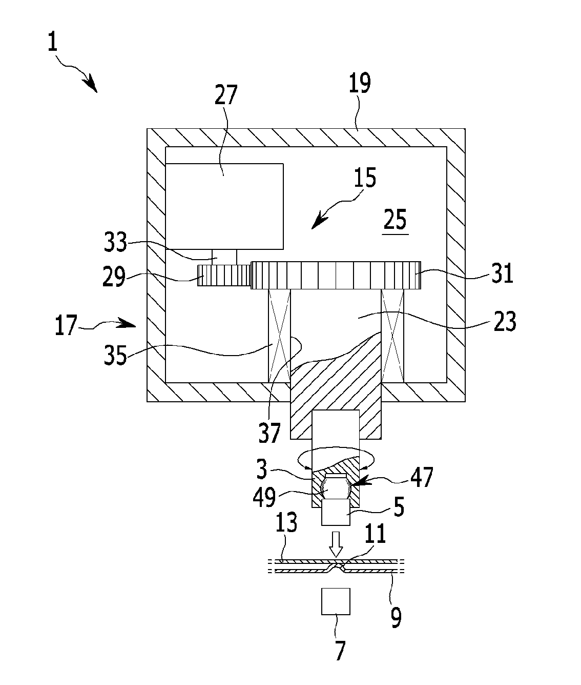
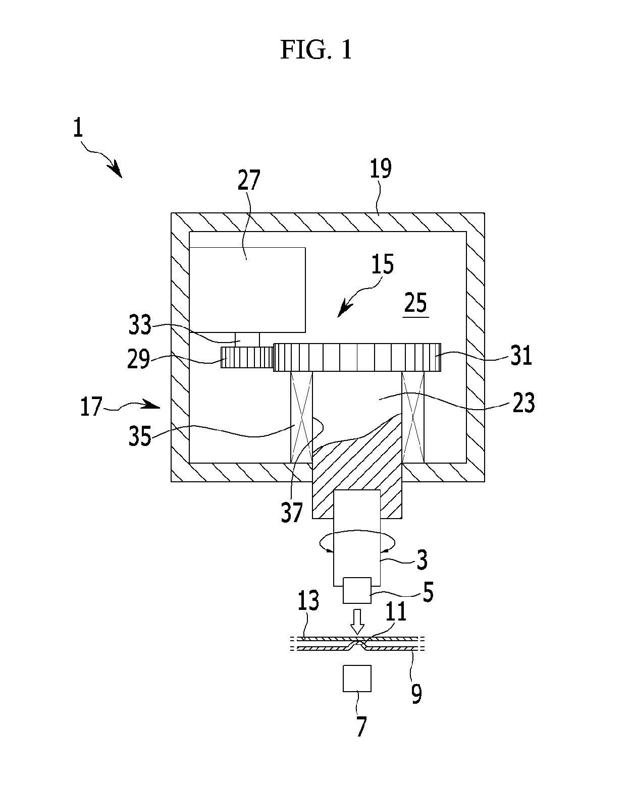
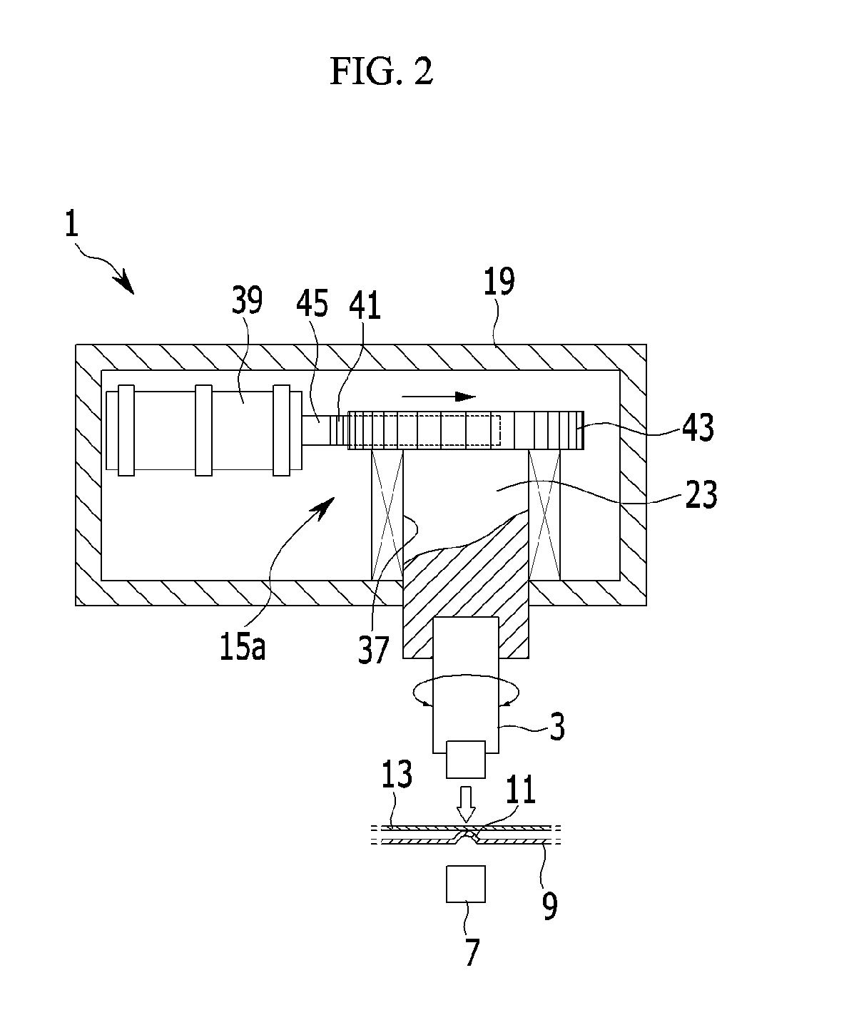
[0046]Hereinafter, exemplary embodiments of the present invention will be described with reference to accompanying drawings.

[0047]The size and thickness of each element are arbitrarily shown in the drawings, but the present invention is not necessarily limited thereto, and in the drawings, the thickness of layers, films, panels, regions, etc., are exaggerated for clarity.

[0048]Also, in order to clarify the present invention, parts that are not connected with the description will be omitted, and the same elements or equivalents are referred to with the same reference numerals throughout the specification.

[0049]It is understood that the term “vehicle” or “vehicular” or other similar term as used herein is inclusive of motor vehicles in general such as passenger automobiles including sports utility vehicles (SUV), buses, trucks, various commercial vehicles, watercraft including a variety of boats and ships, aircraft, and the like, and includes hybrid vehicles, electric vehicles, plug-i...


PUM

PropertyMeasurementUnit
Speedaaaaaaaaaa

Abstract

A projection welding gun device includes an upper welding tip and a lower welding tip that are combined with a gun body through a shank, where the upper welding tip presses an upper panel corresponding to a protrusion portion that is formed on a lower panel to weld the upper and lower panels, and a rotation unit that is rotated by a driving portion is disposed between the gun body and the shank to rotate the shank.

Description

CROSS-REFERENCE TO RELATED APPLICATION[0001]This application claims under 35 U.S.C. §119(a) priority to and the benefit of Korean Patent Application No. 10-2014-0046124 filed in the Korean Intellectual Property Office on Apr. 17, 2014, the entire contents of which are incorporated herein by reference.BACKGROUND[0002]1. (a) Field of the Invention[0003]The present invention relates to a welding gun device, more particularly, a projection welding gun device that applies pressure to a protrusion portion that is formed in a welding portion of a metal member and applies current through the protrusion portion to concentrate resistance heat therein.[0004]2. (b) Description of the Related Art[0005]In general, during a manufacturing process of a vehicle, various structural parts such as a vehicle body panel molded by a press and the like are bonded by a method such as welding to complete an integrated vehicle body, the completed vehicle body is painted and rust-prevented throughout the surfac...

Claims


Application Information

Patent Timeline
IPC IPC(8): B23K11/11
CPCB23K11/115
Inventor CHO, DO-WOONLIM, CHAE WONCHO, YONG JOON
Owner HYUNDAI MOTOR CO LTD
Features
  • Generate Ideas
  • Intellectual Property
  • Life Sciences
  • Materials
  • Tech Scout
  • Unparalleled Data Quality
  • Higher Quality Content
  • 60% Fewer Hallucinations
Learn More