Method and apparatus for supporting product during cutting

a technology of supporting products and products, applied in metal working apparatus, stock shearing machines, manufacturing tools, etc., can solve the problems of reducing log support, continuous motion, and insufficient compression of clamping logs, so as to improve both the end cut and center cut quality, reduce waste, and reduce length

a technology of supporting products and products, applied in metal working apparatus, stock shearing machines, manufacturing tools, etc., can solve the problems of reducing log support, continuous motion, and insufficient compression of clamping logs, so as to improve both the end cut and center cut quality, reduce waste, and reduce length

US20150298331A1Inactive Publication Date: 2015-10-22PAPER CONVERTING MASCH CO INC

Image

  • Method and apparatus for supporting product during cutting
  • Method and apparatus for supporting product during cutting
  • Method and apparatus for supporting product during cutting

Examples


Embodiment Construction

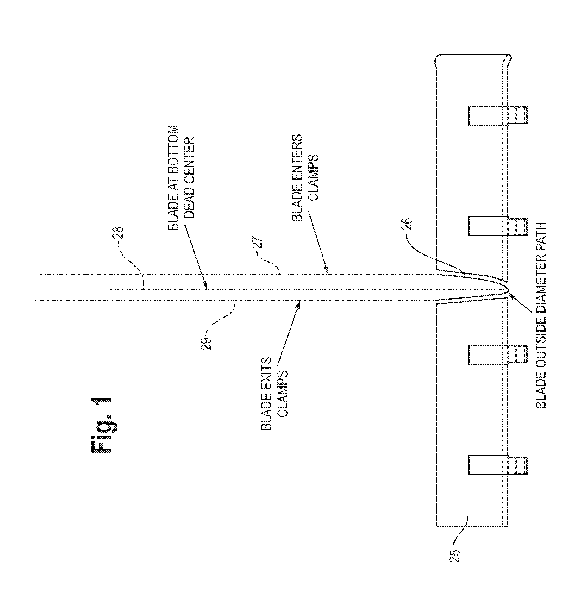
[0039]FIG. 1 illustrates a prior art product support or clamp 25 which has been used with continuous motion log saws of the type which are described in U.S. Pat. Nos. Re. 30,598 and 6,123,002. An elongated product (not shown), e.g., a log of toilet paper or kitchen towel, is advanced longitudinally over the product support from right to left. The product support is provided with a generally V-shaped notch 26. The movement of a cutting blade of a log saw is represented by the dashed lines 27, 28, and 29, which trace the movement of the outside diameter of the cutting blade. The blade passes generally transversely through the product while the blade also moves in the longitudinal direction of the moving product so that the blade moves longitudinally at the same speed as the product. The line 27 represents the path of the cutting blade as it enters the product and the V-shaped notch 26 and moves longitudinally to the left. The line 28 represents the position of the cutting blade at its...


PUM

PropertyMeasurementUnit
lengthaaaaaaaaaa
lengthaaaaaaaaaa
axial movementaaaaaaaaaa

Abstract

Elongated product is cut while the product moves longitudinally by a cutting blade which passes through the product and which also moves longitudinally with the product. The product is supported by first and second product supports which are spaced apart in the longitudinal direction to provide a gap through which the cutting blade passes. The product supports are mounted for movement in the longitudinal direction and move longitudinally as the cutting blade passes through the gap.

Description

RELATED APPLICATION[0001]This application is a divisional application of co-pending U.S. patent application Ser. No. 13 / 312,652, filed Dec. 6, 2011, entitled Method and Apparatus for Supporting Product During Cutting, the priority of which is claimed under 35 U.S.C. §§120 & 121.BACKGROUND[0002]This invention relates to a method and apparatus for supporting product during cutting, and more particularly, to supporting product for cutting by a saw which transversely severs material such as a log of convolutely wound bathroom tissue or kitchen toweling in single or multiple lanes, rolls of wipes material, and the like.[0003]In the production of rolls of bathroom tissue, kitchen toweling, or wipes, a jumbo sized parent roll of web material is unwound and rewound into an elongated log which has the diameter of the final product. The log is cut into individual rolls of bathroom tissue, kitchen toweling, or wipes by a saw. When the individual rolls are produced, two end trim pieces are also...

Claims


Application Information

Patent Timeline
22 Oct 2015
Publication
US20150298331A1
IPC
B26D1/56; B26D7/01
CPC
B26D7/01; B26D1/56; B26D3/16; B26D7/0683; Y10T83/0515; Y10T83/4734
Inventors
DIEHR, ERIC P.; GUSSERT, CORY P.