Apparatus and Method for Forming a Design on an Expanded Bead Foam Article

a technology of expanded foam and apparatus, applied in the field of apparatus and method for forming a design on an expanded bead foam article, can solve the problems of added cost, typically not reproducing in a crisp, well defined form, etc., and achieve the effect of increasing the axial pressur

Active Publication Date: 2015-10-22
SONOCO DEV INC
View PDF15 Cites 0 Cited by
  • Summary
  • Abstract
  • Description
  • Claims
  • Application Information

AI Technical Summary

Benefits of technology

The patent describes a method of molding a design onto the end of a foam article. This is done by moving the end die plate inward, which increases the pressure on the foam beads and helps them to expand and form the desired design. This technique can create precise, detailed designs on the end of foam articles and can improve their overall quality.

Problems solved by technology

However, because the circular ends of the mold are located in an opposite orientation to the open-close direction of the die tools, the logo typically doesn't reproduce in a crisp, well defined form because of the low foam pressure imposed on the ends.
Logos can be added later as a secondary process, but this represents added cost.

Method used


Image

  • Apparatus and Method for Forming a Design on an Expanded Bead Foam Article
  • Apparatus and Method for Forming a Design on an Expanded Bead Foam Article
  • Apparatus and Method for Forming a Design on an Expanded Bead Foam Article

Examples


Embodiment Construction

[0022]While this invention may be embodied in many forms, there is shown in the drawings and will herein be described in detail one or more embodiments with the understanding that this disclosure is to be considered an exemplification of the principles of the invention and is not intended to limit the invention to the illustrated embodiments.

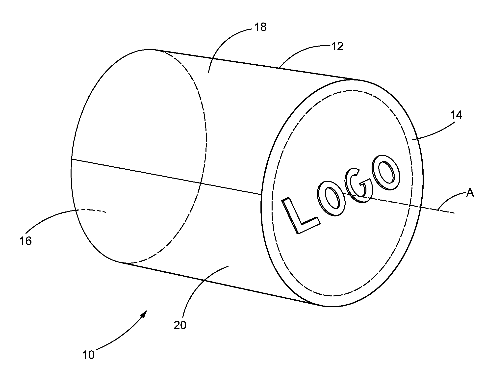
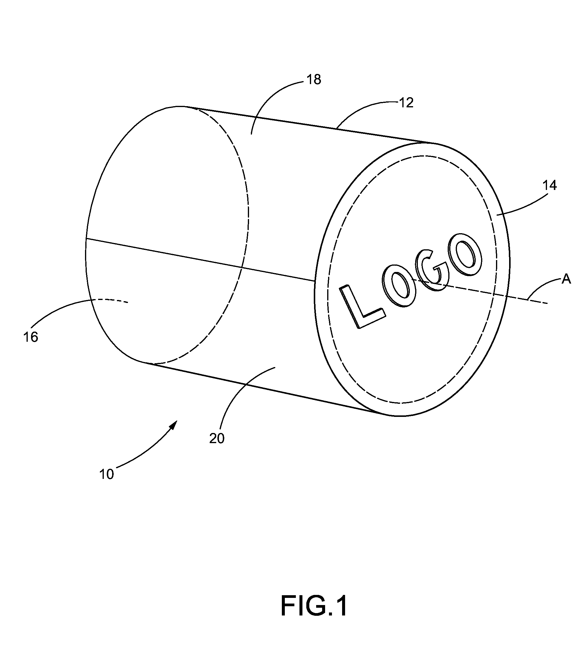
[0023]FIG. 1 is a perspective view of an expanded bead foam article 10 as might be produced using a steam chest mold. The article 10 comprises a sidewall 12, a first endwall 14 and an opposing second endwall 16. The sidewall 12 is cylindrical and the endwalls 14, 16 are circular. The article 10 is longitudinal and may define an axis A extending from endwall to endwall.

[0024]The sidewall 12 in turn may comprise an upper sidewall 18 and a lower sidewall 20 delineated from each other by a seam 22. The seam 22 is a vestige of the steam chest molding process, in which an upper die half 40 forms the upper sidewall 18 and the upper half of each endwall...


PUM

PropertyMeasurementUnit
diameteraaaaaaaaaa
diameteraaaaaaaaaa
pressureaaaaaaaaaa

Abstract

An apparatus and method for forming a design on an expanded bead foam article such as an exercise roller is provided.

Description

BACKGROUND OF THE INVENTION[0001]1. Field of the Invention[0002]This invention patent relates to steam chest molding and the manufacture of expanded bead foam articles. More particularly, this invention relates to an apparatus and method for forming a design on an expanded bead foam article such as an exercise roller.[0003]2. Description of the Related Art[0004]Expanded foam bead molded articles, such as the popular cylindrical rollers used for exercise and therapy, may be produced in steam chest molding machines similar to injection molding machines. Exercise rollers can be any size suitable for exercising or therapy. Typical exercise rollers are about twelve to thirty-six inches long and have circular ends that are about six inches in diameter.[0005]The exercise rollers are most often molded on the long (axial) dimension. That is, each tool die half is shaped like half of a cylinder, with the open / close direction of the mold being in the longitudinal (axial) direction.[0006]Compan...

Claims


Application Information

Patent Timeline
Patent Type & Authority Applications(United States)
IPC IPC(8): B29C44/10
CPCB29C44/10B29C44/3426B29C33/04B29C33/048B29C44/343B29C44/3434B29C44/58
Inventor COLE, ROB
Owner SONOCO DEV INC
Why Eureka
Try Eureka