Multi-stage tilting and multi-rotor flying car

Active Publication Date: 2015-10-22
EXENS
View PDF23 Cites 28 Cited by
  • Summary
  • Abstract
  • Description
  • Claims
  • Application Information

AI Technical Summary

Benefits of technology

[0005]Accordingly, the present invention is conceived to solve the forgoing problems, and an aspect of the present invention is to provide a vertical takeoff and landing (VTOL) flying car which can not only vertically take off in a rotary-wing mode using a plurality of rotary wings attached to a ultralight fuselage and wings of an aircraft and then horizontally fly in a fixed-wing mode by changing a thrust direction of some rotors for a horizontal thrust mode through two or more stages, but also taxi with a light automotive-wheel system like a car.
[0006]Further, another aspect of the present invention is to provide a flying car which is an aircraft including five or more rotors, fixed-wings and a taxiing system, and is a piloted and automatic unmanned system capable of taking off and landing vertically and making a long-distance flight speedily, thereby selectively functioning as a car or an aircraft as necessary.
[0007]In accordance with an aspect of the present invention, there is provided a flying car including a main frame externally shaped like a car or an airplane having a flat surface and a curved surface and internally formed with a grid frame and a skin material; a body mounted at a center of the main frame in consideration of balance; a plurality of rotors mounted to the main frame to face upward, a plurality of wheels mounted to the main frame to face downward, body wings provided at

Problems solved by technology

A conventional rotary-wing aircraft such as a helicopter is capable of taking off and landing vertically even in a narrow area, but consumes much more energy and is slower than a fixed-wing aircraft while movi

Method used


Image

  • Multi-stage tilting and multi-rotor flying car
  • Multi-stage tilting and multi-rotor flying car
  • Multi-stage tilting and multi-rotor flying car

Examples


Embodiment Construction

[0018]Hereinafter, exemplary embodiments according to the present invention will be described with reference to accompanying drawings. Also, terms and words used in the following description and claims have to be interpreted by not the limited meaning of the typical or dictionary definition, but the meaning and concept corresponding to the technical idea of the present invention on the assumption that the inventor can properly define the concept of the terms in order to describe his / her own invention in the best way.

[0019]Further, embodiments described in this specification and elements shown in the drawings are nothing but preferable examples, and do not represent the entirety of the present technical idea. Accordingly, it will be appreciated that they may be replaced by various equivalents and modifications on the filing date of the present invention.

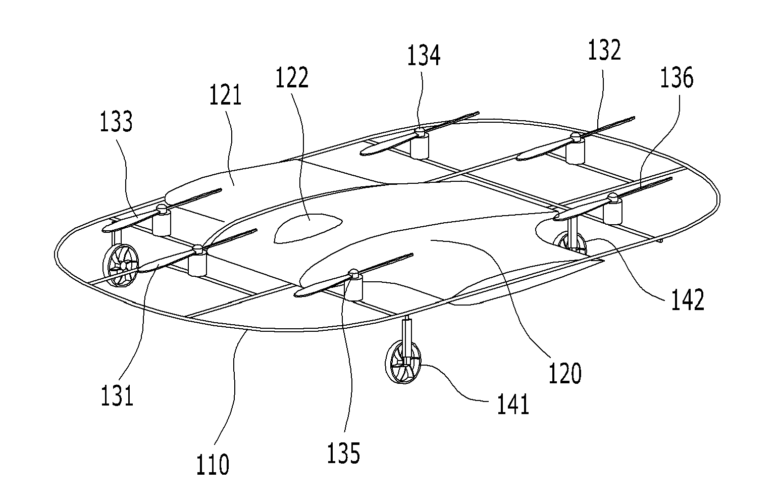
[0020]FIG. 1 is a perspective view of a multi-stage tilting and multi-rotor flying car according to an embodiment of the present inv...


PUM


Abstract

The present invention provides a multi-stage tilting and multi-rotor flying car including: a main frame externally shaped like a rectangle and internally partitioned to have a grid structure; a body mounted at a center of the main frame in consideration of balance; a plurality of rotors mounted to the main frame to face upward; a plurality of wheels mounted to the main frame to face downward; body wings provided at opposite sides of the body; and an automatic driving controller provided in the body and controlling the rotors and the wheels, thereby having effects on spending only the minimum necessary flying time for taking off and landing in a narrow area, and improving flight performance three times higher in flight time and flight speed and five times higher in fight distance than a rotary-wing aircraft such as a helicopter while flying in the fixed-wing mode.

Description

BACKGROUND OF THE INVENTION[0001](a) Field of the Invention[0002]The present invention relates to a multi-stage tilting and multi-rotor flying car, and more particularly to a multi-stage tilting and multi-rotor flying car, which can take off and land vertically and make a long-distance flight speedily with lift and thrust created by five or more rotors through multi-stage tilting.[0003](b) Description of the Related Art[0004]A conventional rotary-wing aircraft such as a helicopter is capable of taking off and landing vertically even in a narrow area, but consumes much more energy and is slower than a fixed-wing aircraft while moving horizontally. On the other hand, a general fixed-wing aircraft has advantages of consuming low energy and flying speedily while moving horizontally, but has disadvantage of requiring a relatively long runway.SUMMARY OF THE INVENTION[0005]Accordingly, the present invention is conceived to solve the forgoing problems, and an aspect of the present invention...

Claims


Application Information

Patent Timeline
IPC IPC(8): B64C27/26B64C27/28B64C29/00B60F5/00
CPCB64C27/26B64C29/0033B64C27/28B60F5/003B60F5/02B64C27/20B64C29/0025B64C37/00B60V3/00
Inventor YOON, KWANG JOON
Owner EXENS
Why Eureka
Try Eureka