Distributed monitoring system and waste management system and method

a technology of waste management system and distribution monitoring system, which is applied in the direction of alarms, resources, applications, etc., can solve the problems of unnecessarily emptying of bins, bin overfilling, poor use of bins,

Inactive Publication Date: 2015-10-22
XORRO
View PDF43 Cites 46 Cited by
  • Summary
  • Abstract
  • Description
  • Claims
  • Application Information

AI Technical Summary

Benefits of technology

[0019]In an embodiment the environmental conditions comprise one or more of the following: whether a door of a bin surround is open, whether a near field transmitter is proximate to the bin; whether there is a fire detected in or near the bin; levels of gases, particles, noise level, temperature, humidity, pollen count, radiation or UV light in the vicinity of the bin.
[0020]In an embodiment the second sensor comprises a pollution sensor, and the processor is also configured to receive a signal form the pollution sensor indicating a pollution level as one or more elements of the environmental factor, and the processor is further configured to periodically transmit the pollution level signal, and or to transmit the pollution level signal upon command. In an embodiment the pollution sensor is arranged to measure air pollution external to the bin.
[0021]In an embodiment the second sensor comprises a “door open” sensor for sensing when a cover or door of the bin surround is open, and the processor is also configured to receive a signal form the “door open” sensor as one or more elements of the environmental factor, and the processor is further configured to monitor for the door open sensor to activate and / or to deactivate, and if a condition in relation to the door sensor is met to transmit a door open signal.
[0022]In an embodiment the second sensor comprises a near field identification sensor, and the processor is also configured to receive a signal form the near field identification sensor indicating whether a near field identifier is proximate to the bin as one or more elements of the environmental factor, and the processor is further configured to periodically transmit an identification signal, or if a condition in relation to the near field identifier being proximate to the bin is met to transmit an identification signal and or to transmit the an identification signal upon command. In an embodiment the condition is that the near field identifier is sensed for more than a predetermined period of time. In this example the waste collector will have a near field identifier, such as an RFID tag, and the timing of the waste collector can be monitored.

Problems solved by technology

This can result in bins that are not full being emptied unnecessarily and bins overfilling.
In turn this results in poor use of the bins, the creation of litter and inefficient management of waste collection from the bins.

Method used


Image

  • Distributed monitoring system and waste management system and method
  • Distributed monitoring system and waste management system and method
  • Distributed monitoring system and waste management system and method

Examples


Embodiment Construction

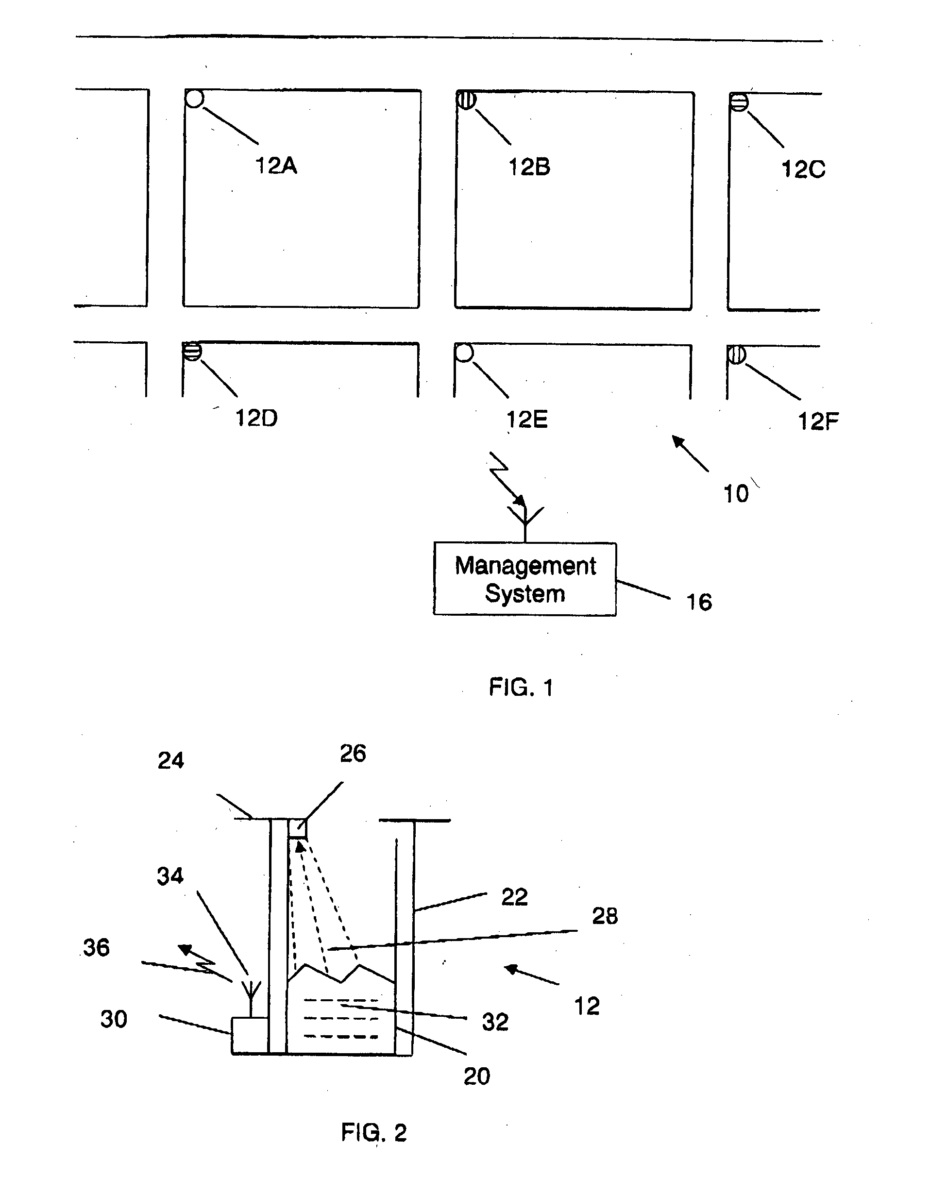
[0074]Referring to FIG. 1, there is shown an area 10 in which there are a plurality of rubbish bins (12A, 12B, 12C, 12D, 12E and 12F). Bins 12A and 12E are indicated as being empty (no shading). Bins 12B and 12F are indicated as being half full (horizontal shading) and bins 12C and 12D are indicated as being full (vertical shading).

[0075]In prior rubbish collection systems, at the end of a period of time a rubbish collector would collect the rubbish from all of these bins.

[0076]In the present invention bins 12C and 12D would be emptied, bins 12A and 12E would not be emptied and the remaining bins 12 B and 12F may be emptied according to a set of criteria. For example a driver of a rubbish collection truck may be directed to take a path from bin 12C to bin 12B, travel past bin 12E to bin 12D. On this route bins 12C and 12D would be emptied, 12B could be emptied as the truck is travelling past, but the truck would not stop at 12E.

[0077]Alternatively the driver may go past all the bins...


PUM


Abstract

A monitoring system comprises a plurality of monitoring stations disposed in or associated with a respective rubbish bin housing or surround. Each monitoring station comprising an identifier, a sensor for monitoring the bin or a detectable quality of the environment in which the bin is located, a processor for receiving a signal from the sensor and a transmitter for transmitting the signal.

Description

FIELD OF THE INVENTION[0001]The present invention relates to a distributed monitoring system based around rubbish bins and management of the collection of rubbish from rubbish bins.BACKGROUND[0002]In areas of higher density population, such as residential / office, retail and entertainment precincts, municipal organisations, such as local governments provide public rubbish bins for disposal of rubbish. Rubbish bins are also known as litter bins, trash cans and garbage cans. Traditionally these bins are fixed in location and emptied on a regular basis which depends on the extent of use of the bins in an overall sense. Typically this is weekly or daily. However each bin in an area will be used in differing amounts depending on the location of the bin within the collection area, special events and other factors. Aside from one-off collections during or after a special event at a specific location, the timing of collection from the bins, generally, does not vary. As a result the frequency...

Claims


Application Information

Patent Timeline
Patent Type & Authority Applications(United States)
IPC IPC(8): B65F1/14G06Q50/28G06Q50/26H04Q9/00
CPCB65F1/14H04Q9/00G06Q50/28G06Q50/26B65F2210/20H04Q2209/84B65F2210/128B65F2210/1443B65F2210/168H04Q2209/20G06Q10/06B65F2210/184
Inventor LUXFORD, LEN
Owner XORRO
Why Eureka
Try Eureka