Solar energy collectors and methods for solar energy systems

a solar energy system and solar collector technology, applied in solar heat collector details, lighting and heating apparatus, hybrid energy generation, etc., can solve the problems of high operating cost, limited heat pump, and insufficient ambient air heating of heat pump,

Inactive Publication Date: 2015-10-22
BUSHONG JR JAMES HOWARD
View PDF1 Cites 0 Cited by
  • Summary
  • Abstract
  • Description
  • Claims
  • Application Information

AI Technical Summary

Benefits of technology

is therefore to provide sufficient heat, utilizing one or more of the solar collectors of the present invention, to increase the temperature at the outdoor heat pump coil region to vaporize the refrigerant in the outdoor coil as completely as possible for as much of the day as possible, thus maximizing useful energy extraction from the refrigerant at the indoor coil / air handling unit. Avoiding flooded conditions is also beneficial to the mechanical longevity of the compressor by avoiding 2-phase (liquid and vapor) passing through the compressor that is known to cause premature wear on the compressor.

Problems solved by technology

However it is well known that below certain ambient temperatures, a heat pump can no longer heat the ambient air to a level sufficient for a comfortable interior temperature; typically in these cases an electrical resistance heating unit must provide supplemental heating.
The electrical resistance heating is very energy intensive and therefore expensive to operate as well as a major consumer of energy.
Due to the thermodynamic laws, the heat pump is limited to a certain ability to raise the interior air temperature in the home or building compared to the outside ambient air temperature.
However, the geothermal heat pumps require significant initial investment and usually involve substantial and expensive drilling into the ground.
Further limitations of geothermal heat pumps include soil-specific performance / problems with certain soil conditions, corrosion of pipes in the ground, and possibilities of ground-water contamination from the heat-transfer fluid circulating in the underground pipes.

Method used


Image

  • Solar energy collectors and methods for solar energy systems
  • Solar energy collectors and methods for solar energy systems
  • Solar energy collectors and methods for solar energy systems

Examples


example 1

[0044]A static analysis of the heat required to raise conventional non-porous flat plate collectors to increase the temperature of the flat plate, compared to an example of a porous metal absorber plate collector of the present invention is a useful illustration of some of the benefits of the porous absorber plate collector of the present invention. Example calculations for energy (heat) required to raise the temperature by 100 degrees Fahrenheit for 2 examples of the present invention porous absorber plate collector plate compared to conventional non-porous flat collector plates are shown in Table 1:

TABLE 1HeatVolume(Energy)LengthWidthdepth(cubicDensityrequiredFlat plate Type(ft)(ft)(ft)feet)(lbs / ft3)(BTU)non-porous copper310.040.12555613(conventional)porous copper (present310.040.1231.234invention example)non-porous aluminum310.040.12169454porous aluminum (present310.040.1231.284invention example)

The static heat required is observed to be about 80 to 95% less for these examples of...

example 2

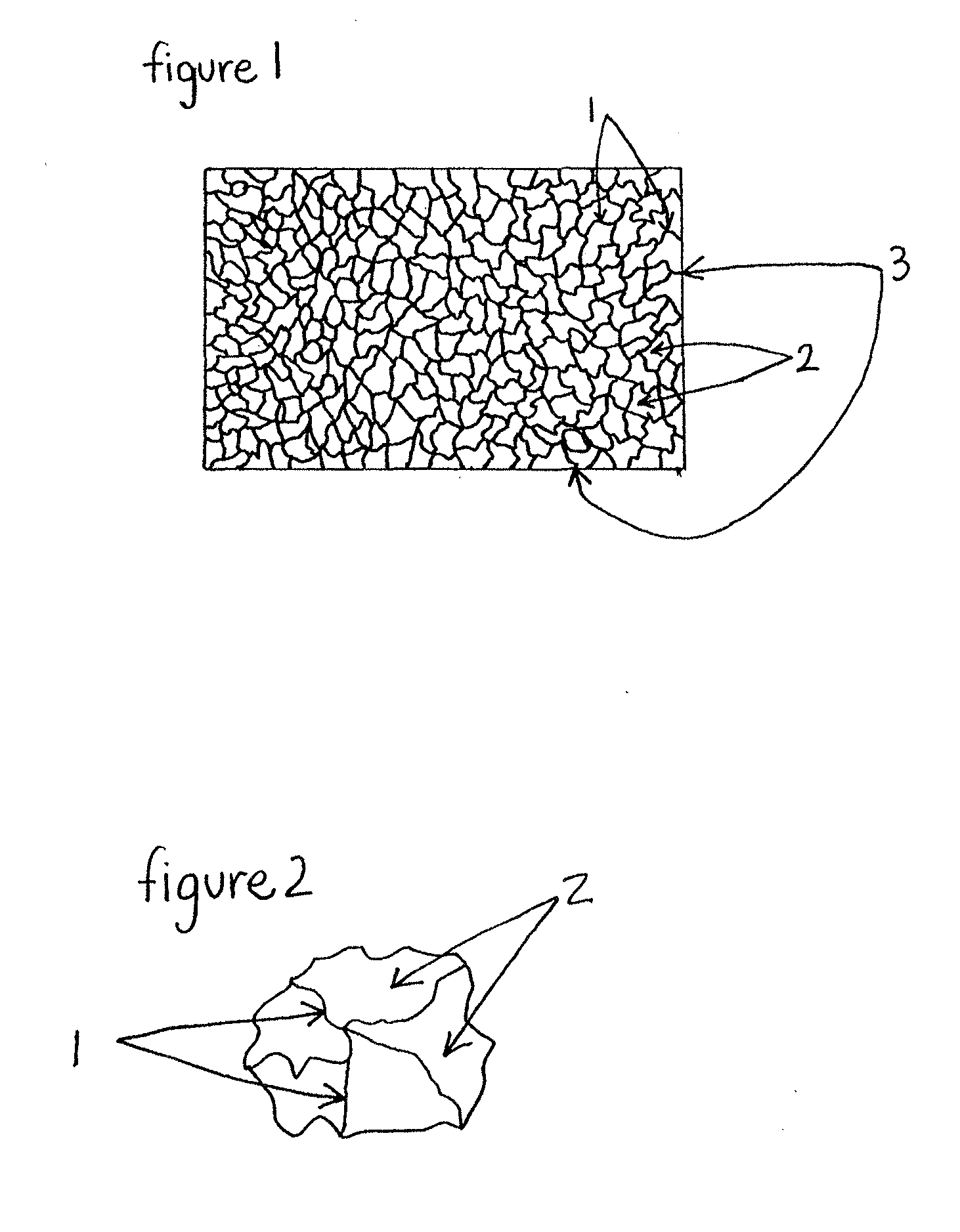
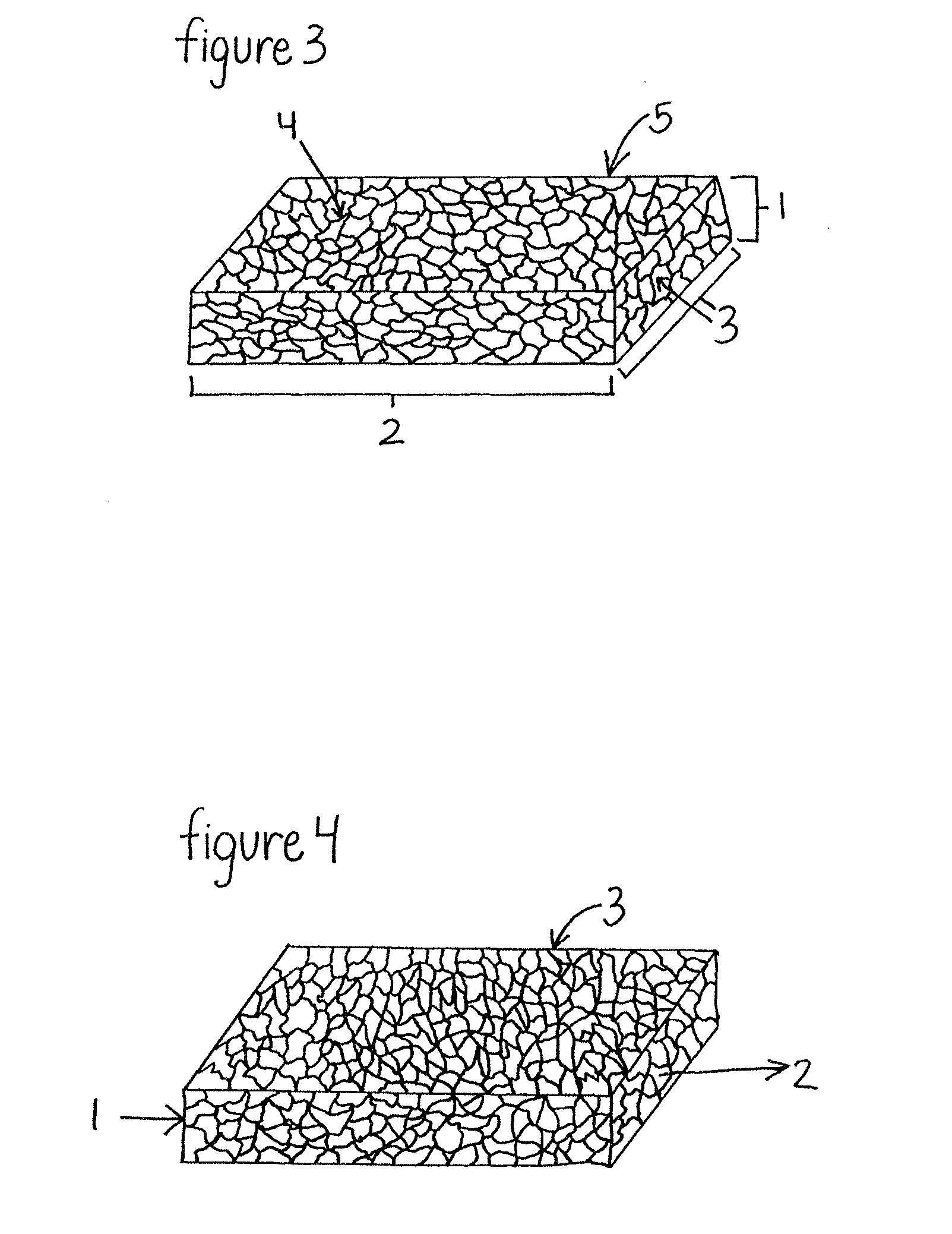
[0045]Two flat plate collectors were prepared. The collector embodiment of the present invention comprised of about 54 mm width by 57 mm long porous copper absorber plate, with a density of about 0.5 g / cc, a thickness of about 5 mm, and a porosity of about 97%. The porous copper absorber plate was spray painted with flat black high temperature paint. The absorber plate was placed inside an aluminum housing, insulated with fiberglass insulation to avoid contact with the aluminum walls, and sealed with a glass lid and silicone caulking A small hole was drilled to insert a thermocouple probe directly inside the copper absorber plate. An identical flat plate collector was prepared, except to use standard black anodized aluminum sheet metal (non-porous) of about 1 mm thick as the absorber plate, with about a 6 mm diameter copper tube inserted under the aluminum sheet absorber plate. A thermocouple probe was inserted into the inside wall of the copper tube. The collectors were placed in t...

example 3

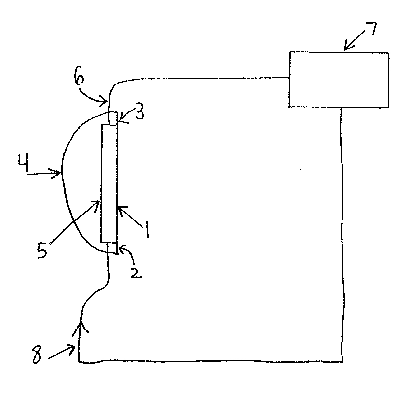
[0046]An embodiment of the Fresnel lens duct concentrating-type solar collector was prepared using a duct of about 300 mm length and about 100 mm width, with 3 Fresnel flat-faced square lenses utilized side by side to form the face of the duct facing the sun. Each Fresnel lens was about 100 mm high by 100 mm wide, and about 2 mm thick, with a groove pitch of about 0.5 mm. A solar reflective film was formed in the shape of a parabola and inserted inside the duct, along the back face. A copper pipe with inside diameter of about 13 mm was painted with flat black high temperature spray paint, and inserted inside the duct in between the solar reflective film along the back face and the Fresnel lens front face. A thermocouple probe was inserted inside the copper pipe, to monitor temperature. The same flat-plate type embodiment of Example 1 with the porous copper absorber plate was used for comparison. The results over a 45 minute test with the collectors placed in the sun yielded the resu...


PUM


Abstract

The present invention offers improved absorber plates for solar energy collectors, improved cover glazings for solar energy collectors, improved concentrating solar energy collectors, and solar energy collection methods that use one or more of the improved solar energy collectors for useful residential, commercial, and industrial applications. The improved absorber plate solar energy collectors utilize a porous metal to improve solar radiant absorption collection and utilization, the improved concentrating solar energy collectors are Fresnel lens faced ducts of various geometries that enable efficient axial length solar energy collection, and the improved cover glazings utilize transparent front and back faces with other improvements to enable increased solar radiant energy collection per unit front face cover area of solar collector.

Description

CROSS REFERENCE TO RELATED APPLICATIONS[0001]This application is a continuation of U.S. non-provisional application Ser. No. 13 / 790,210 filed on Mar. 8, 2013 and entitled Solar Energy Collection Apparatus Containing a Porous Metal Absorber Plate, which claims the benefit of provisional application Ser. No. 61 / 795,155 filed on Oct. 11, 2012 and entitled Apparatus and Methods for Solar Thermal Energy Systems, each of which is incorporated herein by reference in its entirety. This application also claims the benefit of international application serial no. PCT / US13 / 57189 filed on Aug. 29, 2013, the entire disclosure of which is incorporated herein by reference.FIELD OF THE INVENTION[0002]The present invention relates generally to apparatus and methods of improving solar energy collection and utilization. The invention offers improved solar energy collectors and utilization methods that can be especially useful for improving the energy efficiency or the heating performance or a combinati...

Claims


Application Information

Patent Timeline
Patent Type & Authority Applications(United States)
IPC IPC(8): F24J2/08F24J2/30F24J2/24F24S10/30F24S10/40F24S10/70F24S10/80F24S23/30F24S90/00
CPCF24J2/085F24J2/30F24J2/24Y02E10/44F24S10/72F24S2080/503F24S70/12F24S23/31F24S10/80Y02E10/50Y02E10/60Y02B10/20Y02P80/20F24S10/40F24S10/70F24S10/30H02S40/44
Inventor BUSHONG, JR., JAMES HOWARD
Owner BUSHONG JR JAMES HOWARD
Why Eureka
Try Eureka