Surgical microscope system

a microscope and surgical technology, applied in the field of surgical microscope systems, can solve the problems of limiting the rotation range of the camera, unstable camera, easy shaking, etc., and achieve the effects of low camera support rigidity, unstable camera, and easy shaking

Inactive Publication Date: 2015-10-22
MITAKA KOHKI
View PDF16 Cites 8 Cited by
  • Summary
  • Abstract
  • Description
  • Claims
  • Application Information

AI Technical Summary

Benefits of technology

[0006]According to the related art, the long auxiliary arms that support the camera are arranged at a front end of a support arm of a stand, and therefore, a supporting rigidity of the camera is low and the camera is unstable and tends to easily shake. To improve the supporting rigidity of the camera, the auxiliary arms must be shortened to bring the camera closer to the front end of the support arm of the stand. This, however, results in limiting a rotational range of the camera. For example, the auxiliary arms block the photographing direction of the camera when the camera is horizontally oriented.

Problems solved by technology

According to the related art, the long auxiliary arms that support the camera are arranged at a front end of a support arm of a stand, and therefore, a supporting rigidity of the camera is low and the camera is unstable and tends to easily shake.
This, however, results in limiting a rotational range of the camera.

Method used


Image

  • Surgical microscope system
  • Surgical microscope system
  • Surgical microscope system

Examples


Embodiment Construction

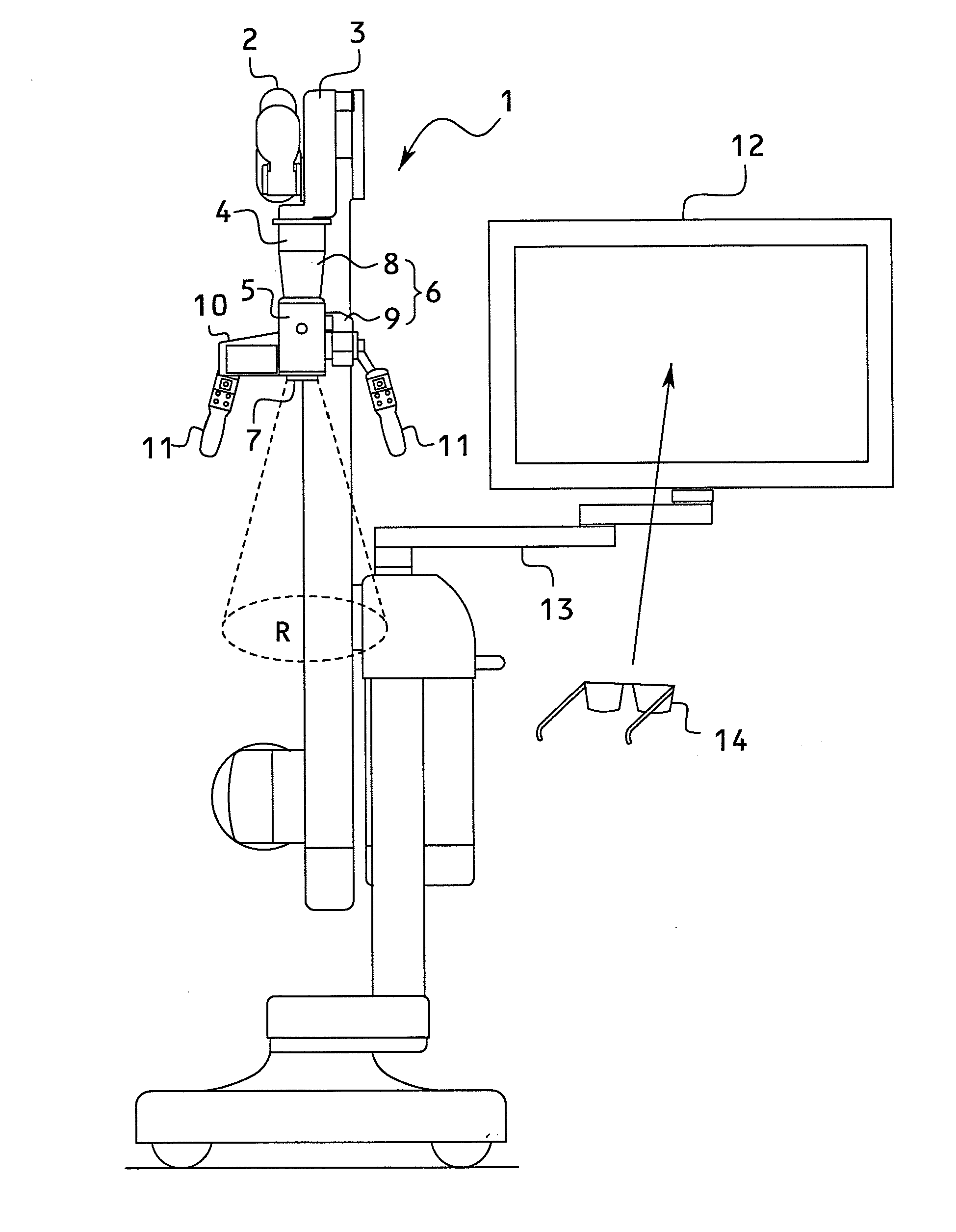
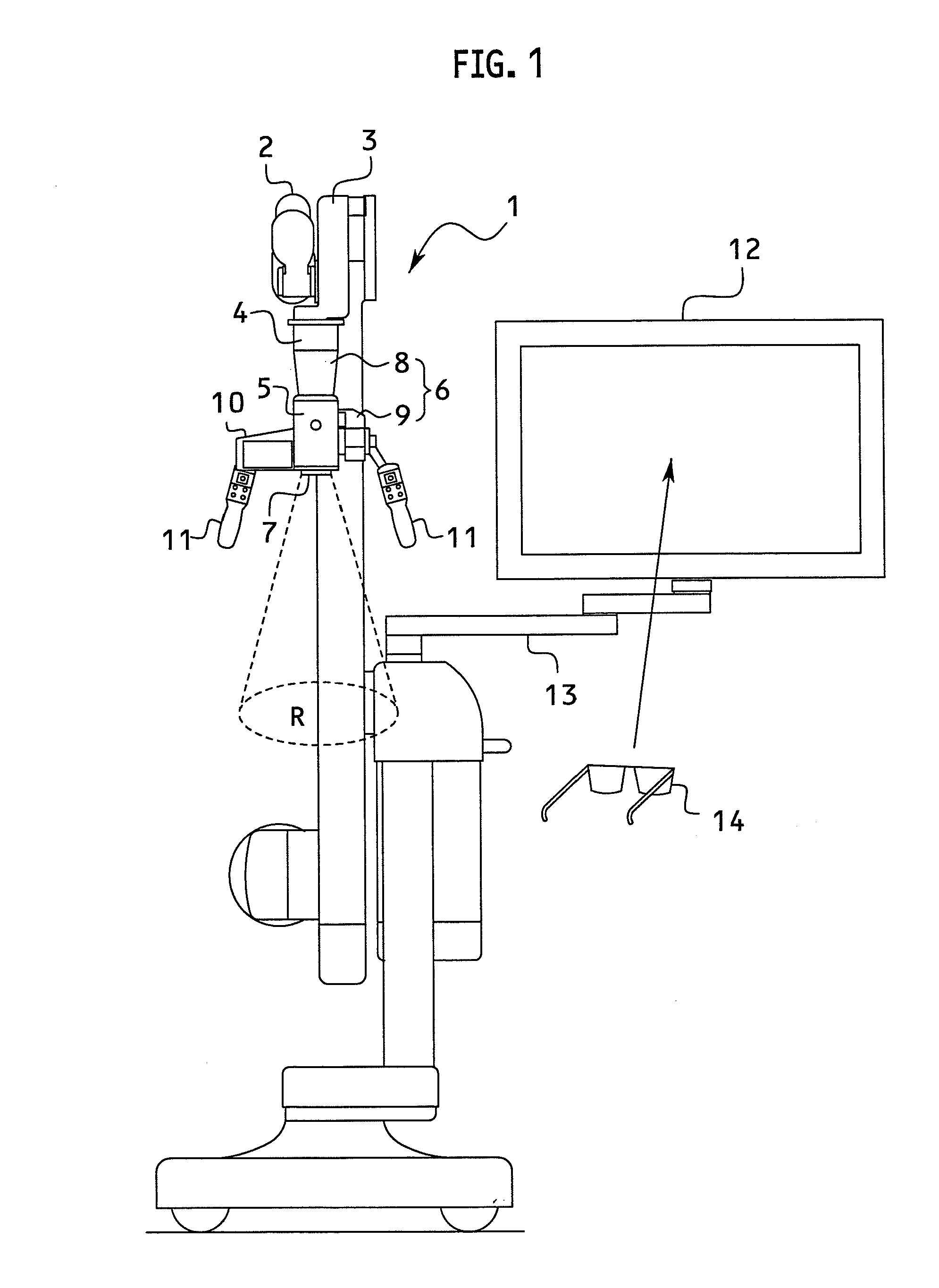
[0014]A surgical microscope system according to an embodiment of the present invention will be explained in detail with reference to FIGS. 1 to 5.

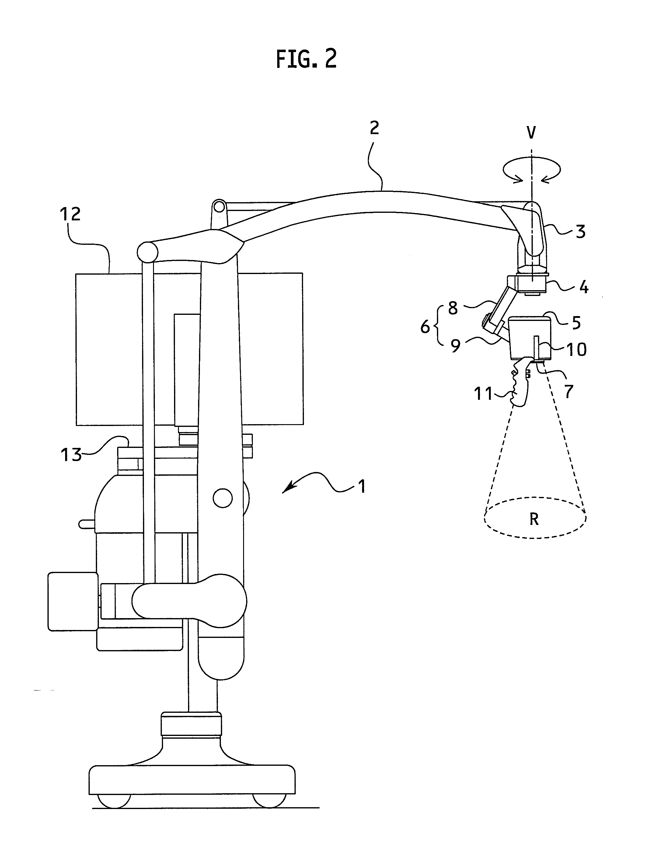
[0015]A stand 1 has a horizontally extending support arm 2. The support arm 2 has a parallel linkage structure to keep a front link 3 vertical when the support arm 2 is moved up and down. The front link 3 has a virtual vertical axis V that passes through a vertical link element (front element) of the parallel linkage structure of the support arm 2. A lower end of the front link 3 has a front member 4 that is rotatable relative to the vertical link element around the vertical axis V.

[0016]A camera 5 is supported by and under the front member 4 through an auxiliary arm 6. Arranged at a lower end of the camera 5 is an objective lens 7 that stereoscopically takes optical images having binocular parallax of an operative field R.

[0017]The auxiliary arm 6 includes a first member 8 and a second member 9. An upper end of the first member 8 is fixed...


PUM


Abstract

A surgical microscope system includes a camera that is rotatable around a first rotation axis and a second rotation axis, the rotation axes being orthogonal to each other, so that a photographing direction of the camera is changeable at a given position. The first rotation axis is inclined with respect to a vertical axis, and therefore, a lower end of a first member is able to be set at a height that does not interfere with the photographing direction when the camera is horizontally oriented.

Description

BACKGROUND OF THE INVENTION[0001]1. Field of the Invention[0002]The present invention relates to a surgical microscope system.[0003]2. Description of Related Art[0004]Some neurosurgical or surgical operations are conducted, instead of by observing an operative field through an eyepiece of a surgical microscope, by taking electronic images of the operative field with a camera supported at a certain height and by observing the electronic images on an electronic image display. The electronic-image-taking and displaying of an operative field may be two-dimensional or three-dimensional. In a case of three-dimensional fashion, an operator must wear exclusive glasses to see three-dimensional images. Seeing two- or three-dimensional images of an operative field on a display releases the operator from putting his or her eyes on the eyepiece of a surgical microscope, thereby expanding the operator's mobility. In addition, it allows not only the operator but also assistants to observe the two-...

Claims


Application Information

Patent Timeline
Patent Type & Authority Applications(United States)
IPC IPC(8): G02B21/36H04N13/04H04N5/232G02B21/00G02B21/22
CPCG02B21/362G02B21/0012H04N13/0429G02B21/367H04N5/23293G02B21/22H04N23/51
Inventor DOI, MASAONAKAMURA, KATSUYUKI
Owner MITAKA KOHKI
Why Eureka
Try Eureka