Micro Fence Adjuster Assembly

a technology of adjuster and fence, which is applied in the direction of metal working equipment, manufacturing tools, wood working equipment, etc., can solve the problems of loss of efficiency and capital, unwillingness to fully utilize table saws,

Active Publication Date: 2015-10-29
SUHLING ROBERT JAMES
View PDF4 Cites 14 Cited by
  • Summary
  • Abstract
  • Description
  • Claims
  • Application Information

AI Technical Summary

Benefits of technology

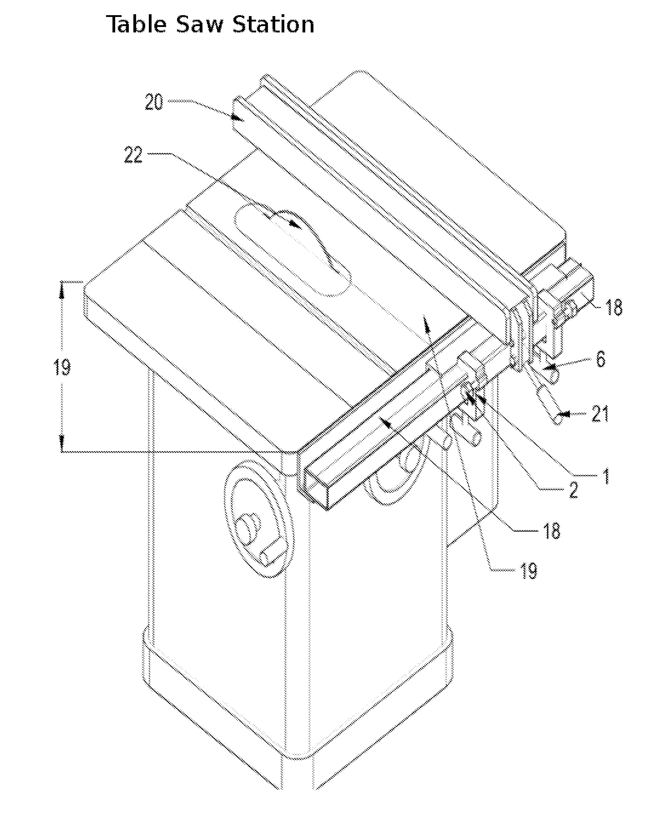
[0031]FIG. 7 is a view of the fence [20] and fence rail [18] with a closer view of the fence lock [21] mechanism. This closer view better shows the advantages of the shape of the main body [1]. One such advantage includes fitting beneath the fence [20] and moving the indexing action toward the operator. This view shows the contact point [23] of the indexing screw [3] upon the fence lock [21].

Problems solved by technology

A table saw can accommodate many different cutting actions through the use of various accessories and techniques, yet some operators are unable or unwilling to fully utilize their table saws; likewise, some operators are not able to properly operate their table saws, resulting in the loss of efficiency and capital.

Method used


Image

  • Micro Fence Adjuster Assembly
  • Micro Fence Adjuster Assembly
  • Micro Fence Adjuster Assembly

Examples


Embodiment Construction

[0016]A carpenter is tasked with replacing multiple cracked shelves in a bookcase, with the stipulation that the replacement shelves must fit into existing dadoes in the bookcase. The carpenter determines the desired dimensions of the finished product, and equips his or her table saw with a T-style fence and multiple iterations of the preferred embodiment. With the aid of a tape measure, the carpenter moves the T-style fence to a position that will cut his or her material at a size that is a quarter-inch larger than the desired shelf and tenon length. After locking the fence, the carpenter installs one iteration of the preferred embodiment in right-of-fence orientation just to the right of the table saw fence lock. The carpenter turns the adjustment knob until the indexing screw makes contact with the fence lock. After powering the saw and with the assistance of a push-stick, the carpenter feeds the work-piece through the cutting plane. The carpenter measures the cut material, and f...


PUM


Abstract

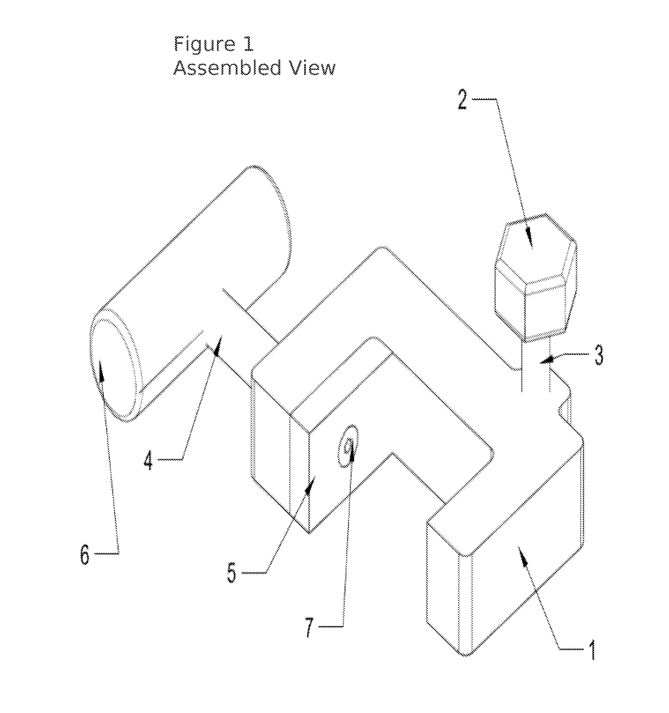
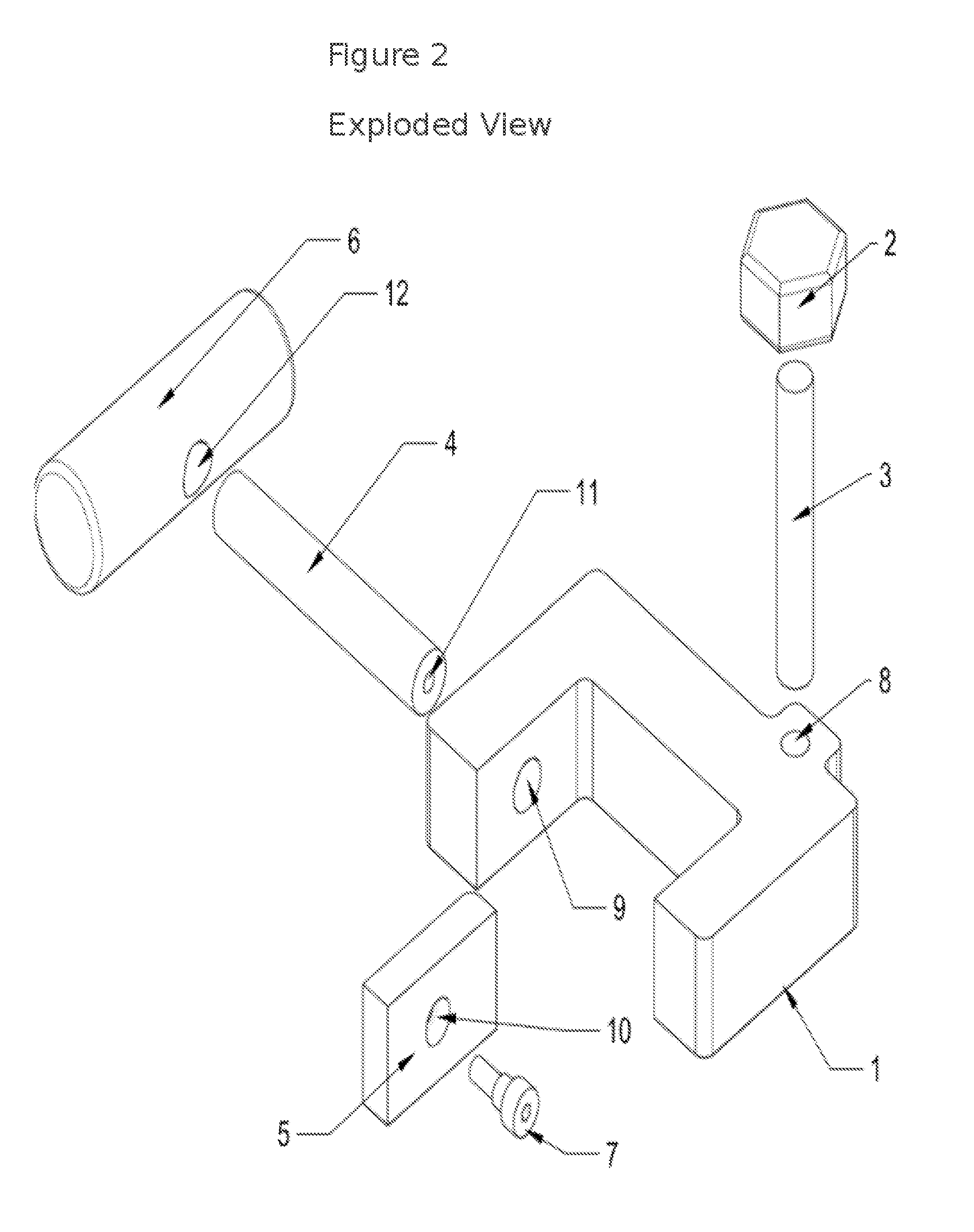
A clamp that is meant to act as a coordinate locator for any number of power tools, but most specifically for use with the Biesemeyer T-style table saw fences. The assembly is comprised of a C-frame which offers the ability to enact a clamping action and the ability to enact an indexing action. The design of the assembly allows not only for the clamping of an imprecise reference point along a table saw fence rail, but also the fine adjustment of indexing a screw against the table saw fence.

Description

RELATED U.S. APPLICATION DATA[0001]I claim protection and the priority of this patent application as extensively as is permitted through the rights granted by provisional patent application No. 61 / 854,683; filed on Apr. 30, 2013PROSPECTIVE US PATENT CLASSES AND SUBCLASSES[0002]83 / 37483 / 43883 / 453144 / 357PUBLICATION CLASSIFICATIONPrior Art Citation(s)[0003]U.S. Pat. No.William M. BiesemeyerJun. 28, 1978269 / 2364,206,910 ARelevant Citation(s)[0004]U.S. Pat. No. 236,239 AEdward L. MorrisMay 21, 1880269 / 181US 20080271583 A1Bor-Yann ChuangMay 4, 2007 83 / 438U.S. Pat. No.Robert P. WelshNov. 19, 2013 83 / 477.28,584,564 B2et al.TECHNICAL FIELD OF THE INVENTION[0005]The present invention relates to accessories for power tools and fixtures for the purposes of positioning and repositioning a workpiece in woodworking and metalworking power tool applications—specifically concerning equipment and assemblies commonly referred to as “position locators” associated with table saws. More specifically, the ...

Claims


Application Information

Patent Timeline
Patent Type & Authority Applications(United States)
IPC IPC(8): B27B27/10B27B27/08B27B27/02
CPCB27B27/10B27B27/08B27B27/02
Inventor SUHLING, ROBERT JAMES
Owner SUHLING ROBERT JAMES
Why Eureka
Try Eureka