Method for monitoring physical parameters of well equipment

a technology for physical parameters and well equipment, applied in the direction of optical detection, survey, borehole/well accessories, etc., can solve the problems of significant risk of cable breakage, cumbersome and time-consuming installation of sensing cables,

Active Publication Date: 2015-10-29
SHELL USA INC
View PDF9 Cites 1 Cited by
  • Summary
  • Abstract
  • Description
  • Claims
  • Application Information

AI Technical Summary

Benefits of technology

[0004]It is an object of the present invention to provide a method for monitoring deformation of a casing or other well equipment using a optical fiber assembly which can be attached quickly to the well casing and such that the optical fiber assembly is adequately protected against breaking during attachment or during deployment in the well.

Problems solved by technology

Such installation of the sensing cable is cumbersome and time consuming with a significant risk of breaking the cable during attachment or during deployment in the well.

Method used


Image

  • Method for monitoring physical parameters of well equipment
  • Method for monitoring physical parameters of well equipment
  • Method for monitoring physical parameters of well equipment

Examples


Embodiment Construction

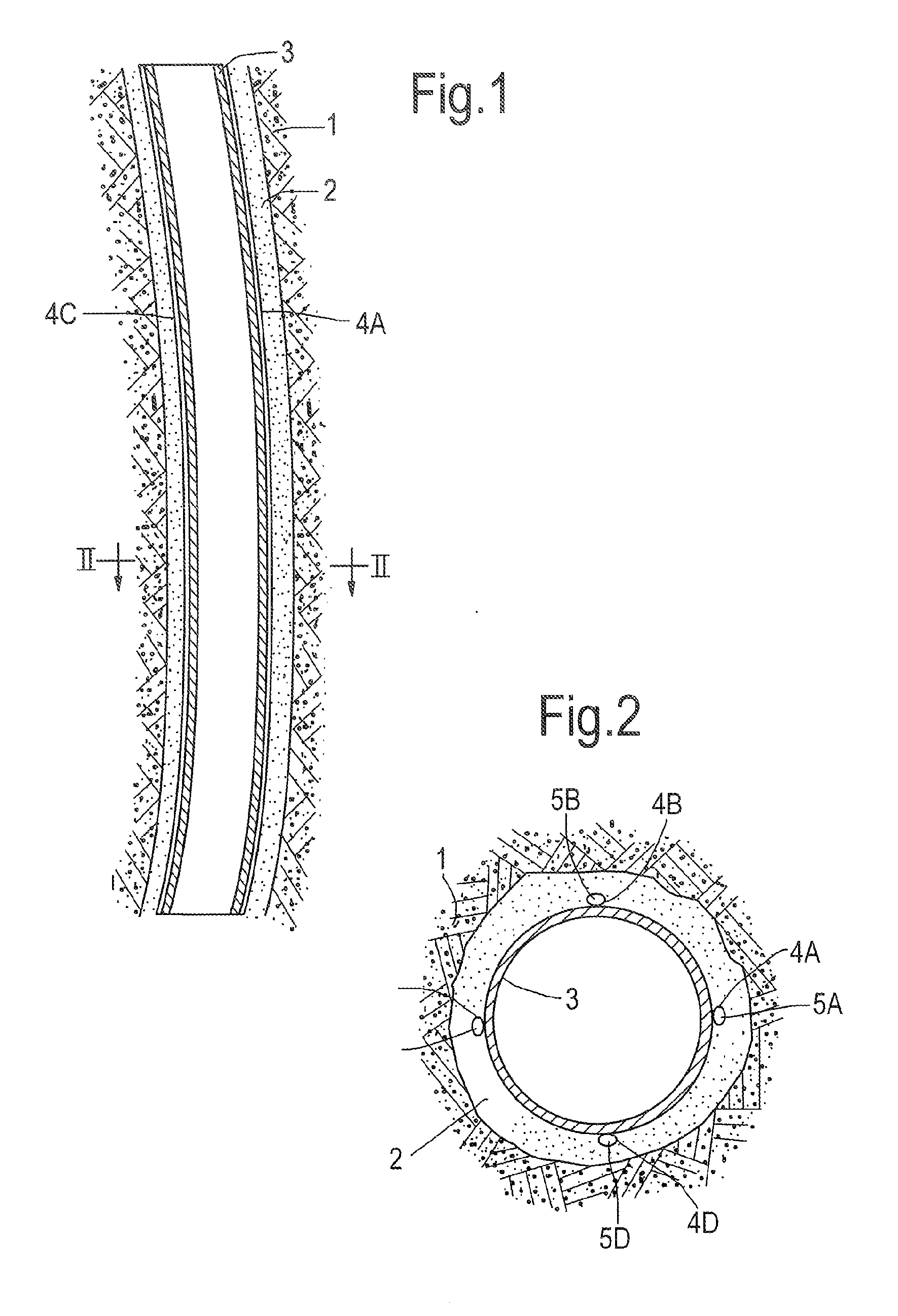
[0023]FIG. 1 shows a curved wellbore 1 in which a bend casing 2 is arranged. The casing 2 is secured within the wellbore 1 by cement 3, which fills the annular space between the outer surface of the casing 2 and the inner surface of the wellbore 1.

[0024]In order to monitor stress, deformation, temperature and other features a series of four rods 4A-4D are embedded in the cement 3 around the casing 2. As illustrated in FIG. 2 each rod has a recess in which an optical strain monitoring fiber 5A-5D is embedded. The rods 4A-4D are preferably made of the same metal as the casing 2.

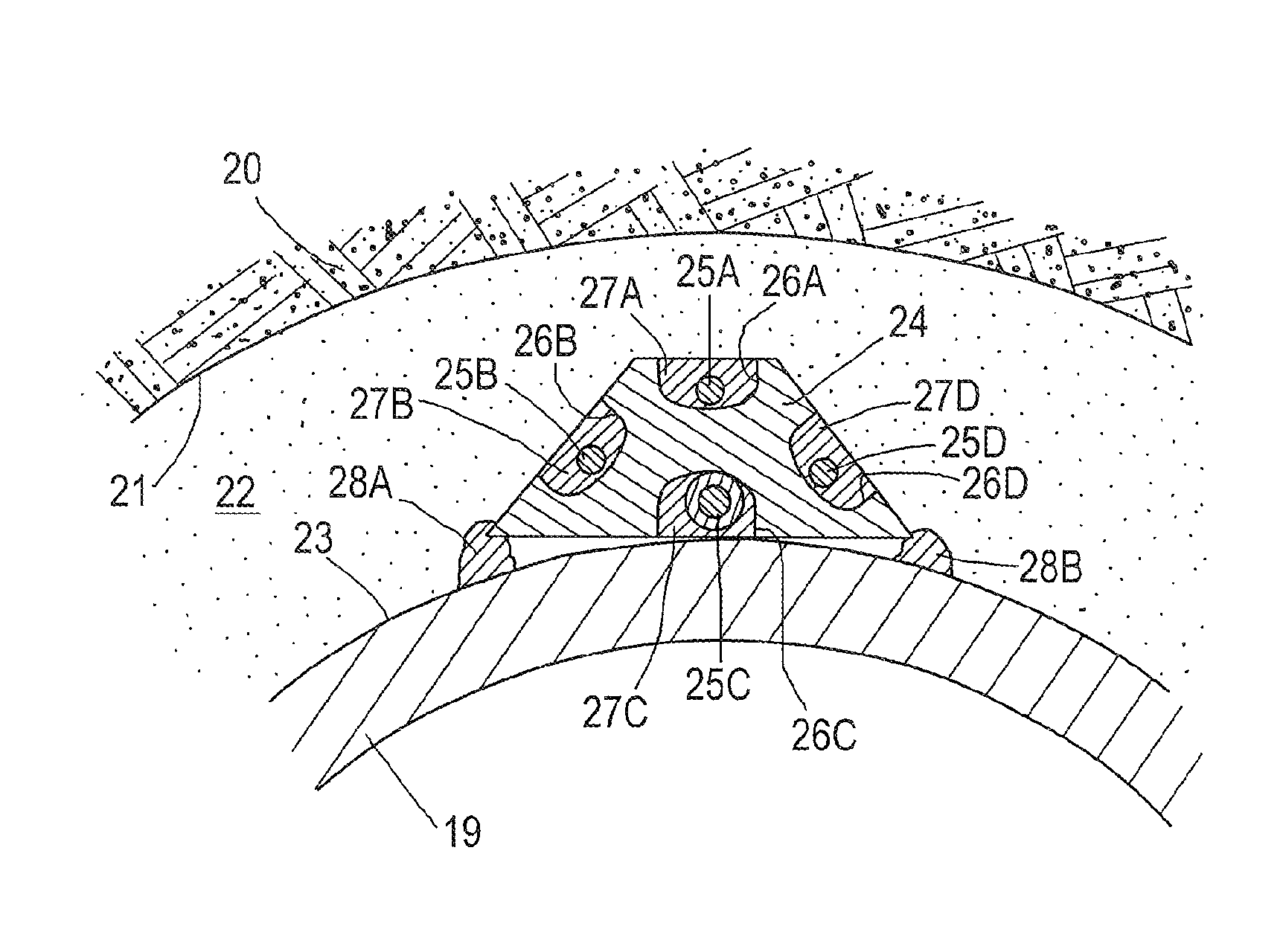
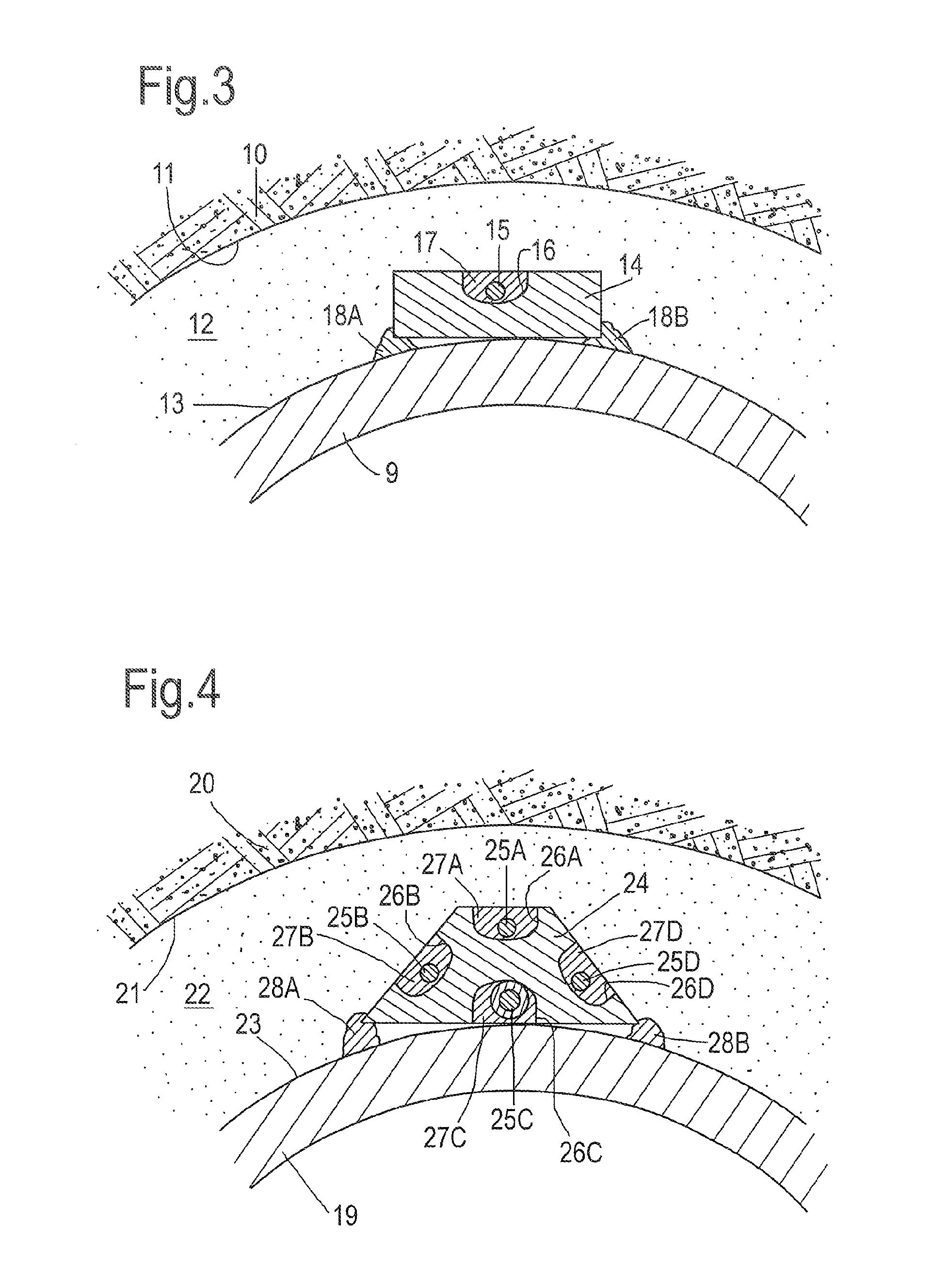
[0025]FIG. 3 shows in more detail a cross sectional view of an alternative embodiment of a rod 14, wherein the rod has a rectangular shape and is arranged in a cement body 12 between the inner surface 11 of a wellbore in an underground earth formation 10 and the outer surface 13 of a casing 9. The rod 14 has a recess 16 in which an optical strain monitoring fiber 15 is embedded within a protective filler 17. Th...


PUM


Abstract

A method of monitoring deformation and other characteristics of a casing or other tubular or cylindrical well equipment in a well traversing an underground formation. The method includes providing a carrier rod having at least one recess extending along at least part of the length of the rod, in which recess an optical fiber assembly for monitoring strain, temperature and / or other physical parameters is arranged, which assembly is along at least part of the assembly's length bonded within the recess; lowering the carrier rod and well equipment simultaneously into the well such that the rod is arranged in an annular space between the well equipment and the wellbore; securing the rod at a plurality of locations distributed along the rod's length to the well equipment; and connecting the optical fiber assembly to an optical signal transmission and reception assembly for monitoring physical parameters of the well equipment.

Description

CROSS REFERENCE TO EARLIER APPLICATIONS[0001]The present application is a Continuation of application Ser. No. 13 / 142,451, filed 2 Aug. 2011, which is a national stage application of International application No. PCT / EP2009 / 067866, filed 23 Dec. 2009, which claims priority of U.S. 61 / 141,738, filed in the U.S. patent office on 31 Dec. 2008. Each one of these earlier applications is incorporated herein by reference.FIELD OF THE INVENTION[0002]The invention relates to a method for monitoring deformation of well equipment.BACKGROUND OF THE INVENTION[0003]The current approach to monitor deformation of a well casing or other well equipment is to attach or glue fiber optical or other sensing cables directly to the well casing or other well equipment. Such installation of the sensing cable is cumbersome and time consuming with a significant risk of breaking the cable during attachment or during deployment in the well.SUMMARY OF THE INVENTION[0004]It is an object of the present invention to...

Claims


Application Information

Patent Timeline
Patent Type & Authority Applications(United States)
IPC IPC(8): E21B47/01E21B47/06E21B43/24E21B47/00E21B47/12
CPCE21B47/01E21B47/0006E21B43/2401E21B43/24E21B47/065E21B17/026E21B43/10E21B47/007E21B47/135E21B47/017E21B47/07E21B43/08G01V8/16
Inventor JAASKELAINEN, KARI-MIKKO
Owner SHELL USA INC
Why Eureka
Try Eureka