

Drive protection circuit, semiconductor module, and automobile
a protection circuit and semiconductor technology, applied in the direction of emergency protection arrangements for limiting excess voltage/current, pulse techniques, lighting and heating apparatus, etc., can solve problems such as adverse influences on switching elements, and achieve the effect of reliably suppressing surge voltag
- Summary
- Abstract
- Description
- Claims
- Application Information
AI Technical Summary
Benefits of technology
Problems solved by technology
Method used
Image

Examples
first embodiment
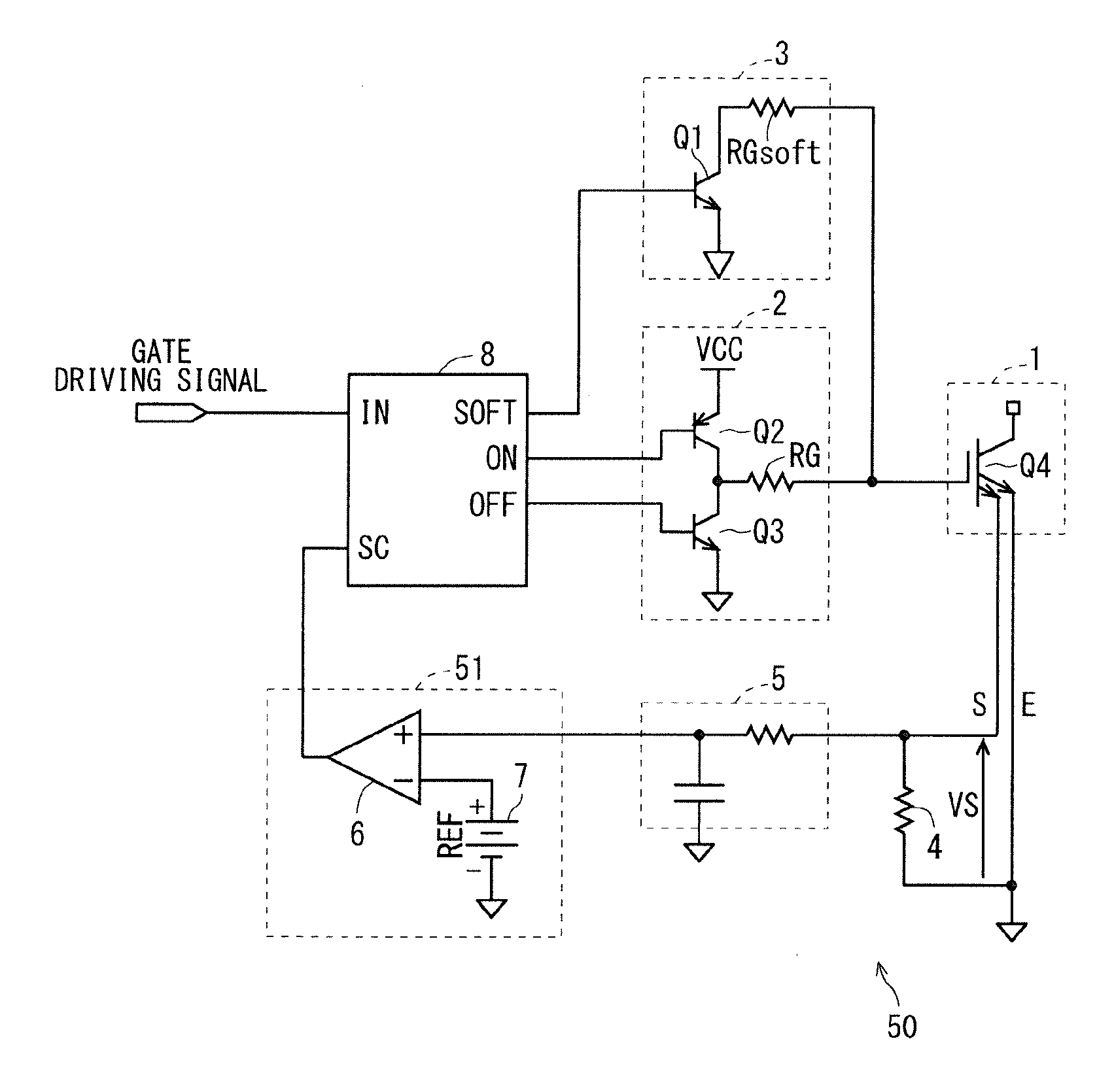
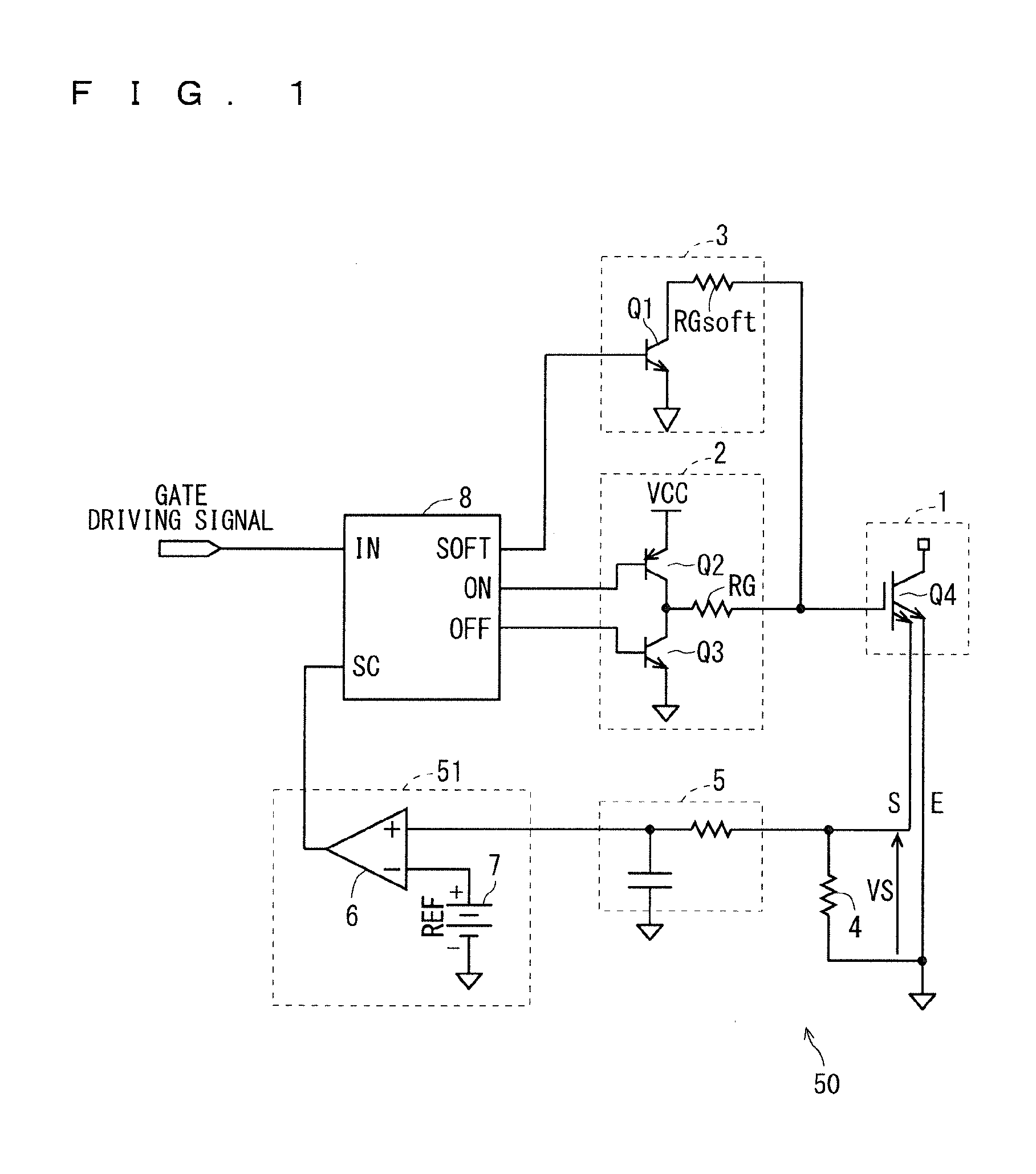
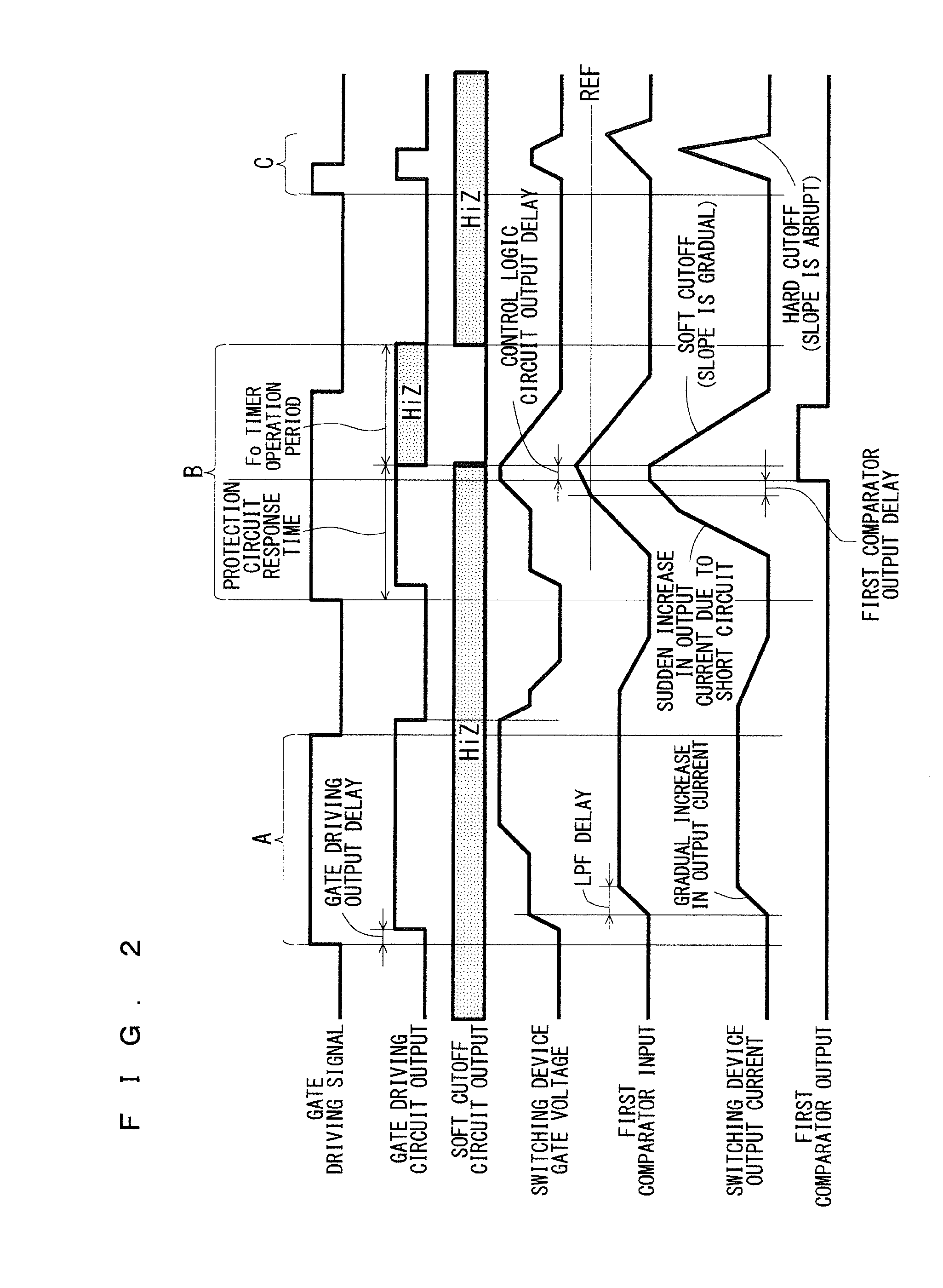
[0031]First, prior to description of a drive protection circuit according to a first embodiment of the present invention, a drive protection circuit related to that (hereinafter referred to as a “related drive protection circuit”) will be described. FIG. 1 is a circuit diagram illustrating a configuration of the related drive protection circuit, and FIG. 2 is a diagram illustrating an operation timing of the related drive protection circuit.
[0032]The related drive protection circuit is a circuit that drives and protects a switching element Q4 of a switching device 1 and is configured to include, as shown in FIG. 1, a gate driving circuit (drive circuit) 2, a soft cutoff circuit 3, a sense resistor 4, a low pass filter (LPF) 5, a first comparator 6, a power supply 7 having a reference voltage REF, and a control logic circuit 8 collectively controlling these.
[0033]Among these structural components, the structural components except for the above-mentioned gate driving circuit 2 (namely...
second embodiment
[0090]FIG. 14 is a circuit diagram illustrating a configuration of a drive protection circuit according to a second embodiment of the present invention, and FIG. 15 is a diagram illustrating an operation timing of the drive protection circuit. In the drive protection circuit according to the second embodiment, the same components as or similar components to those described in the first embodiment are denoted by the same references, and differences are mainly described below.
[0091]The drive protection circuit according to the second embodiment is the drive protection circuit according to the first embodiment as shown in FIG. 8 provided with a third comparator 16 and a power supply 17 having a reference voltage Vmirror, instead of the timer circuit 11.
[0092]In the drive protection circuit according to the second embodiment having such configuration, a mirror period of the switching element Q4 is used instead of the response time of the overcurrent protection circuit 50 as described ab...
third embodiment
[0099]FIG. 18 is a circuit diagram illustrating a configuration of a drive protection circuit according to a third embodiment of the present invention, and FIG. 19 is a diagram illustrating an operation timing of the drive protection circuit. In the drive protection circuit according to the third embodiment, the same components as or similar components to those described in the first embodiment are denoted by the same references, and differences are mainly described below.
[0100]The drive protection circuit according to the third embodiment is the drive protection circuit according to the first embodiment shown in FIG. 8 in which the timer circuit 11 receives the gate voltage of the switching element Q4 instead of the gate driving signal.
[0101]In the drive protection circuit according to the third embodiment having such configuration, a period of time (hereinafter “rise-to-off time”) from rising of the gate voltage of the switching element Q4a to turning OFF the gate driving signal i...
PUM
 Abstract
Description
Claims
Application Information