Safety device for a street lamp system

a safety device and street lamp technology, applied in outdoor lighting, sustainable buildings, lighting and heating apparatus, etc., can solve the problems of high product cost, inefficiency, and dedicated wiring, and achieve the effect of effective re-using existing wiring

Active Publication Date: 2015-10-29
SPI TECNO
View PDF3 Cites 2 Cited by
  • Summary
  • Abstract
  • Description
  • Claims
  • Application Information

AI Technical Summary

Benefits of technology

The present invention provides a safety device for use in a street lamp, which can collect and supply clean energy to the power grid. It allows for easy and economical upgrading of existing lighting systems to ensure higher energy efficiency. The safety device is designed to remain safe even if the power grid incurs damage. Each street lamp is fitted with a current generator and a DC / DC stabilizer to regulate the current supplied to the grid, maximizing power transfer from renewable energy converters. If the line has multiple phases, the post switches can select the correct phase pair to improve energy transfer from the grid to the street lamps. This solution allows for effective reuse of existing wirings without requiring costly work.

Problems solved by technology

The solutions disclosed in US2008 / 0137327 require a very high product cost in the former case and, in the latter case, a subdivision of the lighting system into different zones, the installation of one inverter per zone, and a dedicated direct current wiring between the posts of each zone.
This system has the drawback that the street lamps may be powered on at different times. Moreover, this system has the drawback that it requires one inverter for each post and an RS485 serial communication system that requires a dedicated wiring.
This system appears to be efficient when all the street lamps connected to the low-voltage network are handled as a single group, but becomes inefficient if they have to be divided into subgroups to be controlled separately; in this latter case, in fact, one inverter per subgroup will be needed.
US2008 / 0137327, GB 2449102 and GB 2388974 all suffer from the drawback that no safety measures are taken in the event that the line is damaged, so that the system is subject to the risk of fire and the service personnel is subject to the risk of being harmed by electricity.

Method used


Image

  • Safety device for a street lamp system
  • Safety device for a street lamp system
  • Safety device for a street lamp system

Examples


Embodiment Construction

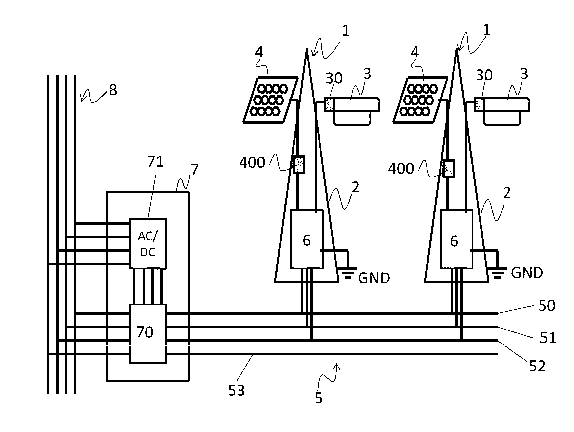
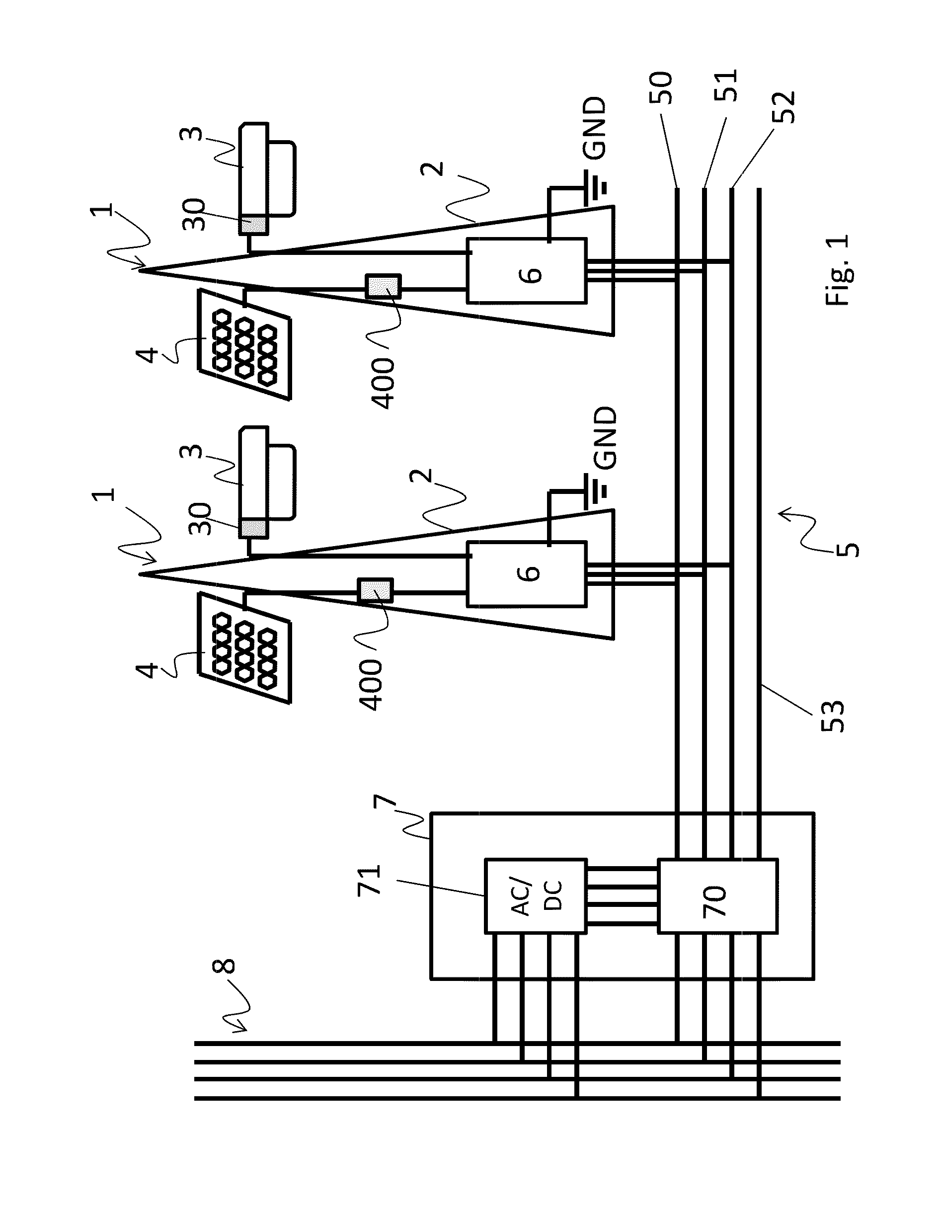
[0046]FIG. 1 schematically shows a public lighting system according to an example.

[0047]The system of FIG. 1 comprises a group of street lamps 1, each comprising a post 2 on which a lamp 3 and a solar panel 4 are fitted.

[0048]In the following description, the term “lamp” will refer to any lighting device capable of generating a luminous flux. For the purposes of the present invention, the lamp may be, for example, an incandescent lamp, a discharge lamp, an arc lamp, a neon lamp, a LED (Light Emitting Diode) lamp, an OLED (Organic LED) lamp, etc.

[0049]In the example of FIG. 1, the lamp is a low-consumption LED lamp that needs direct current power. Since in the example of FIG. 1 the lamps are powered by an alternating current (AC) power line 5, the lamp 3 is fitted with an AC / DC rectifier 30 which allows it to be connected to an alternating current line.

[0050]The solar panel 4 of FIG. 1 is of the photovoltaic type and includes a plurality of cells which transform the photons of solar ...


PUM


Abstract

A safety device for use in a street lamp, includes a first connection to a power grid (5), second connections to at least two external units (3,4), a first unit (3) of at least two units being adapted to draw current and a second unit (4) of at least two units being adapted to generate a potential difference. The safety device further includes a switch (6) adapted to switch between a first position, in which the first unit (3) is connected to the power line (5) to draw current from the power line, and a second position, in which the second unit (4) is connected to the power line to apply the potential difference to wires of the power line. The safety device further includes a communication system adapted to detect the presence of a safety signal on the power line and to switch the switch (6) to the first position in the event that the safety signal is missing or faulty.

Description

CROSS-REFERENCE TO RELATED APPLICATIONS[0001]This application is a divisional of U.S. application Ser. No. 13 / 634,423, filed Oct. 1, 2012, which claims priority to PCT Application No. PCT / IB2011 / 051065, filed Mar. 14, 2011, which claims priority to Italian Application No. MI2010A000417, filed Mar. 15, 2010, which are incorporated herein by specific reference.TECHNICAL FIELD[0002]The present invention relates to device for use in a street lamp, in particular a safety device for public lighting systems, such as those including solar panels, aeolian generators or voltage generators in general, for collecting energy to be supplied to the power grid.[0003]The invention specifically relates to devices according to the preamble of claim 1.PRIOR ART[0004]Public lighting systems are known wherein a plurality of street lamps are fitted with discharge lamps powered through a single-phase or three-phase alternating current line.[0005]The voltage of this line is regulated by a voltage regulator ...

Claims


Application Information

Patent Timeline
Patent Type & Authority Applications(United States)
IPC IPC(8): H05B37/03F21Y101/00
CPCH05B37/03F21S9/03F21S9/04F21V23/04F21W2131/103Y02B20/72H02J2300/22H02J2300/24H02J3/381Y02E10/56H05B47/20H02J3/44F21S8/085F21S9/043H02J3/40
Inventor PENNISI, DARIODE ANGELIS, BERARDINO
Owner SPI TECNO
Why Eureka
Try Eureka