Hydrogen production process

a technology of hydrogen production process and ammonia, which is applied in the field of hydrogen production process, can solve the problems of troublesome ammonia handling, and achieve the effects of convenient and convenient handling, clean source of energy, and convenient us

Active Publication Date: 2015-11-26
NEW TECH CO LTD
View PDF1 Cites 1 Cited by
  • Summary
  • Abstract
  • Description
  • Claims
  • Application Information

AI Technical Summary

Benefits of technology

[0014]The hydrogen production process in accordance with the present invention is capable of producing hydrogen, which is a clean source of energy, easily and conveniently without using ammonia. In addition, the hydrogen-substituted mayenite and the conductive mayenite are both non-toxic powdered substances, and are therefore extremely easy to handle and have an very high level of safety.
[

Problems solved by technology

Unfortunately, the conventional processes of producing hydrogen by catalytic decomposition of ammonia as described in Patent Documents 1 and 2, have a problem in that handling of ammonia is extremely trouble

Method used


Image

  • Hydrogen production process
  • Hydrogen production process
  • Hydrogen production process

Examples


example 1

i) Preparation of Katoite

[0027]First, 200 ml of ion-exchanged water was put into a reactor (separable flask) having a capacity of 1 liter. Next, 9 g of aluminum powder (trade name: #150, manufactured by MINALCO. LTD.) and 12 g of calcium hydroxide (manufactured by Wako Pure Chemical Industries Ltd.) were added to the reactor, followed by stirring. After completion of production of hydrogen gas, the ion-exchanged water was filtered, and a solid content obtained by the filtration was dried at a temperature of 70° C. in air. Katoite was thus obtained.

ii) Preparation of Hydrogen-Substituted Mayenite

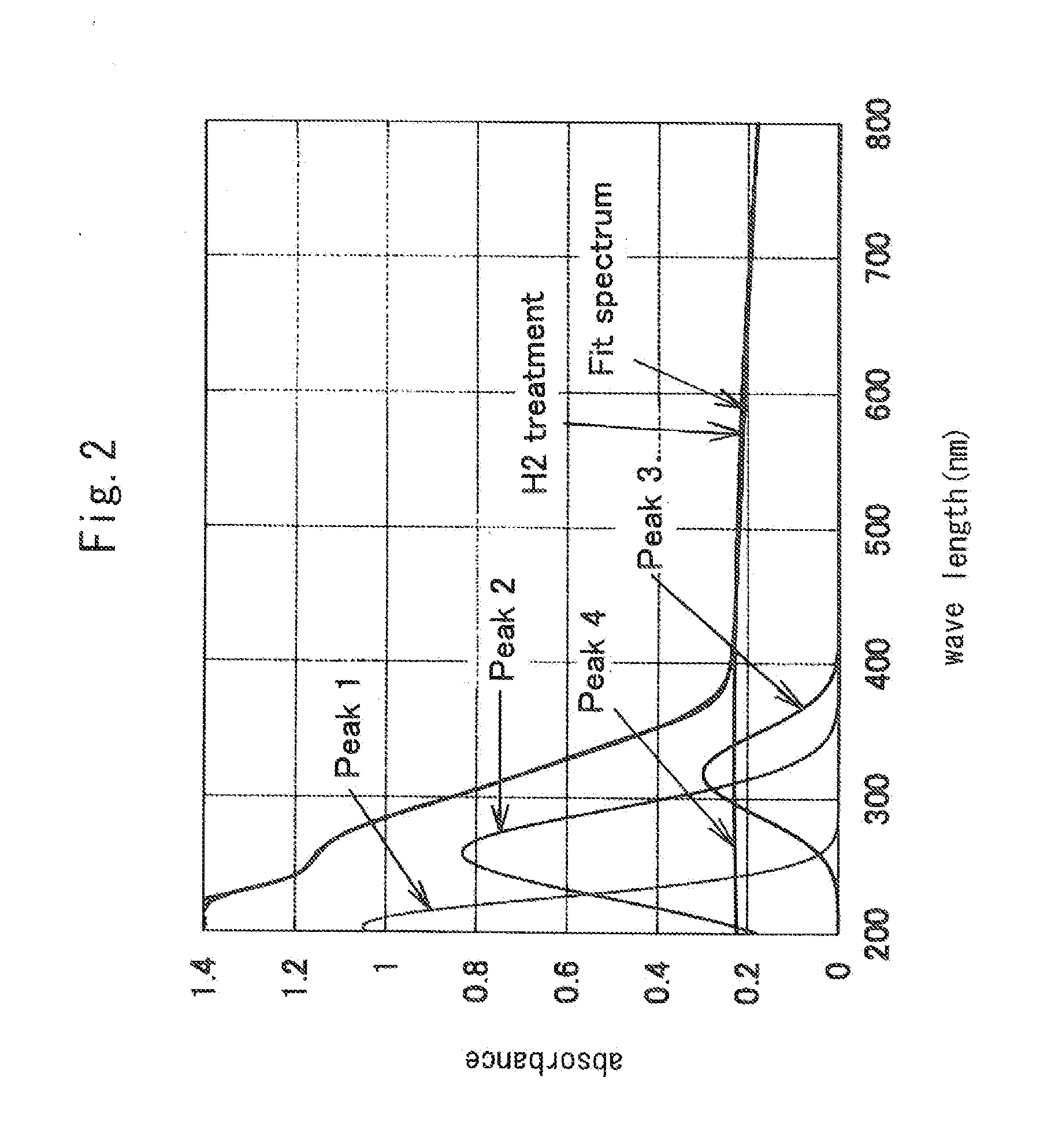
[0028]The resultant katoite was calcined at a temperature of 1300° C. in a hydrogen atmosphere for 2 hours to produce hydrogen-substituted mayenite (Ca24Al28O644+.4H−) . A sample of the calcined product was subjected to X-ray diffraction measurement using an X-ray diffractometer, MaltiFlex, manufactured by Rigaku Corporation and subjected to measurement of a visible-UV reflectance spectrum us...

example 2

[0032]Hydrogen-substituted mayenite (Ca24Al28O644+.4H−) obtained by step ii) of Example 1 was irradiated with ultraviolet rays to obtain conductive mayenite (Ca24Al28O644+.4e−). The ultraviolet irradiation was conducted using a low pressure mercury lamp, with a distance from the lamp to a sample being 6.5 cm, with the irradiation time being 60 minutes.

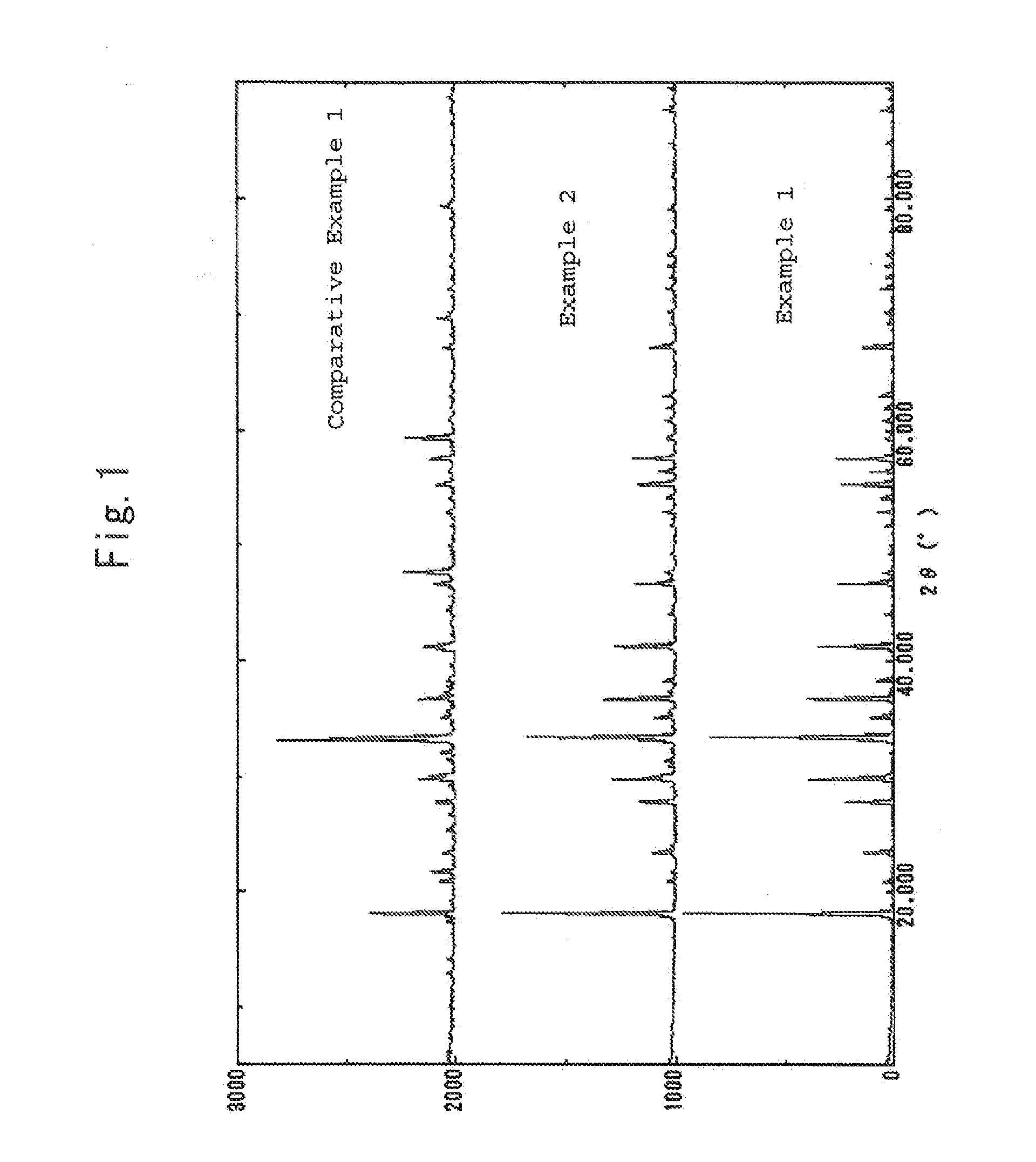
[0033]Conducive mayenite was also subjected to measurement of X-ray diffraction and measurement of a visible-UV reflectance spectrum in the same manner as in step ii) of Example 1.

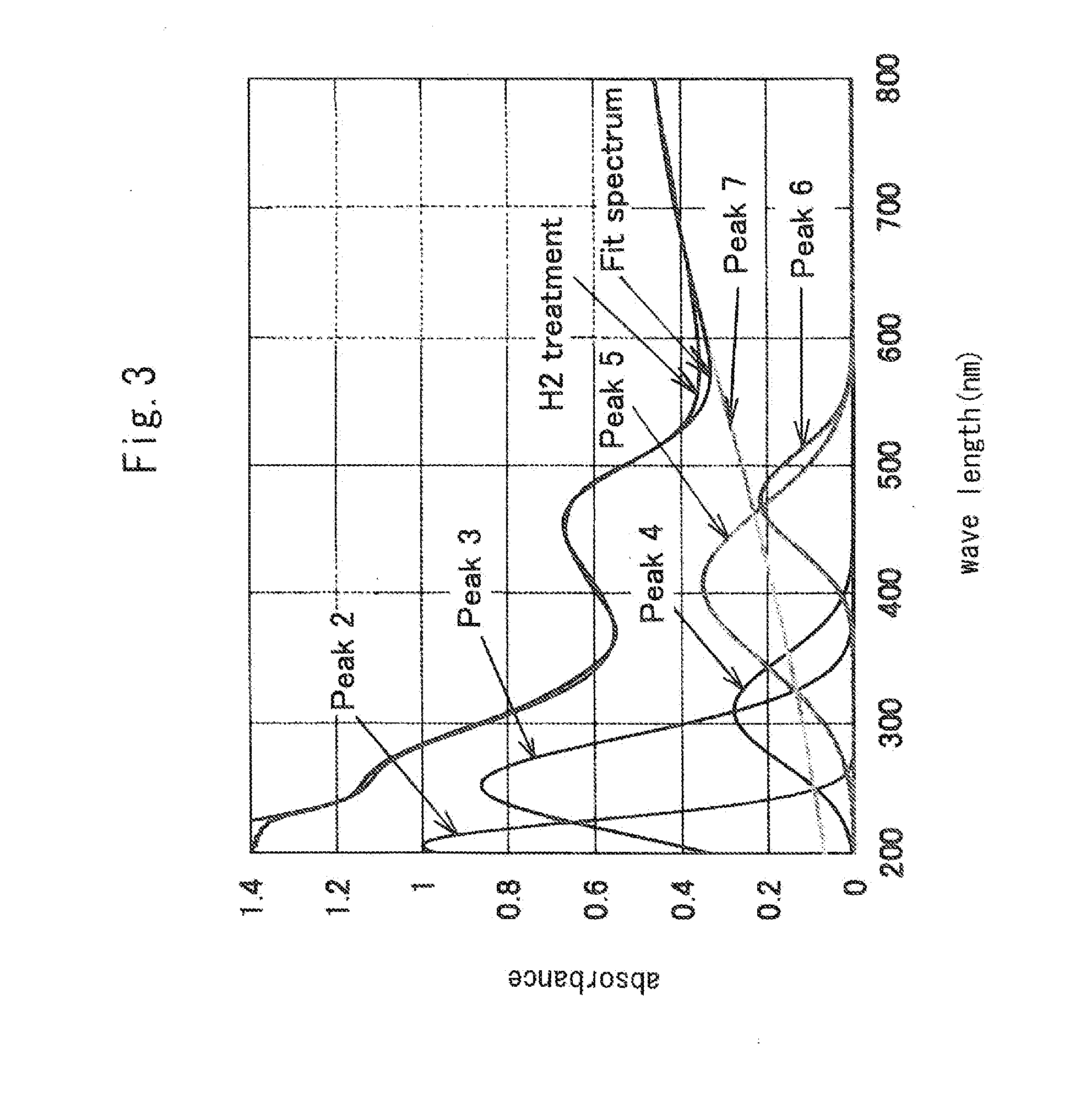
[0034]The measurement results of X-ray diffraction are shown in FIG. 1. As seen from FIG. 1, the sample showed peaks characteristic of mayenite, thereby being confirmed to have the structure of mayenite. FIG. 3 shows measurement results of the visible-UV reflectance spectrum. This sample shows a spectrum separated into three components having peaks at positions around 200, 250, and 310 nm, respectively. Compared to the sample of Comparative Example 1 describe...


PUM


Abstract

The present invention provides a hydrogen production process, which is capable of producing hydrogen, which is a clean source of energy, simply and conveniently without using conventionally-used ammonia, with an extremely high level of safety. In accordance with the present invention, hydrogen is produced by substituting hydrogen for free oxygen in mayenite (Ca24Al28O644+.2O2−) to obtain hydrogen-substituted mayenite (Ca24Al28O644+.4H) and reacting the resultant hydrogen-substituted mayenite (Ca24Al28O644+.4H) with water to produce hydrogen, and hydrogen is produced by substituting hydrogen for free oxygen in mayenite (Ca24Al28O644+.2O2−) to obtain hydrogen-substituted mayenite (Ca24Al28O644+.4H), irradiating the resultant hydrogen-substituted mayenite (Ca24Al28O644+.4H) with ultraviolet rays to obtain conductive mayenite (Ca24Al28O644+.4e), and reacting the resultant conductive mayenite (Ca24Al28O644+.4e) with water to produce hydrogen.

Description

TECHNICAL FIELD[0001]The present invention relates to a hydrogen production process using mayenite having a specific structure.BACKGROUND ART[0002]In recent years, there have been many proposals to use hydrogen as a clean source of energy. For example, fuel cell automobiles that run on hydrogen as a fuel have been developed. Exhaust gas from hydrogen-powered fuel cells does not contain nitrogen oxides, particulate matters, carbon dioxide, and the like, which exhaust gas from internal-combustion engines contains. Thus, fuel cells draw attention as a clean source of power that is capable of suppressing environmental pollution and global warming.[0003]However, hydrogen is large in volume while being stored, and therefore means for supplying hydrogen is of a problem in, for example, automobile fuel cells.[0004]Patent Document 1 discloses a process of producing hydrogen by decomposing ammonia, etc. Patent Document 1 also describes an apparatus for producing hydrogen for use in a fuel cel...

Claims


Application Information

Patent Timeline
IPC IPC(8): B01J19/12C01B3/06H01M8/06C01F7/164
CPCB01J19/123C01B3/061H01M8/0606Y02E60/36C01F7/164C01P2002/72C01P2002/84Y02E60/50
Inventor HIKAZUDANI, SUSUMUWAKUI, ATSUSHIHIRAO, KAZUYUKIFUKUI, TOSHIMINAKAMOTO, JUNKOVISBAL MENDOZA, HEIDY H.
Owner NEW TECH CO LTD
Why Eureka
Try Eureka