Tire theft alarm system

Active Publication Date: 2015-11-05
DENSO CORP
View PDF6 Cites 10 Cited by
  • Summary
  • Abstract
  • Description
  • Claims
  • Application Information

AI Technical Summary

Benefits of technology

[0010]In this way, since the first alarm can be transmitted to the mobile device with the use of the door-control vehicular device operated at a time of at least travelling driven power is in an OFF state, the necessity for operating the TPMS vehicular device when the travelling driven power is in a

Problems solved by technology

However, the technique using light and sound as described above may not be effective for notifying of an abnormality to a user when the distance between a vehicle's parking position and the user's position (for example, residence) is longer.
Acco

Method used


Image

  • Tire theft alarm system
  • Tire theft alarm system
  • Tire theft alarm system

Examples


embodiment 1

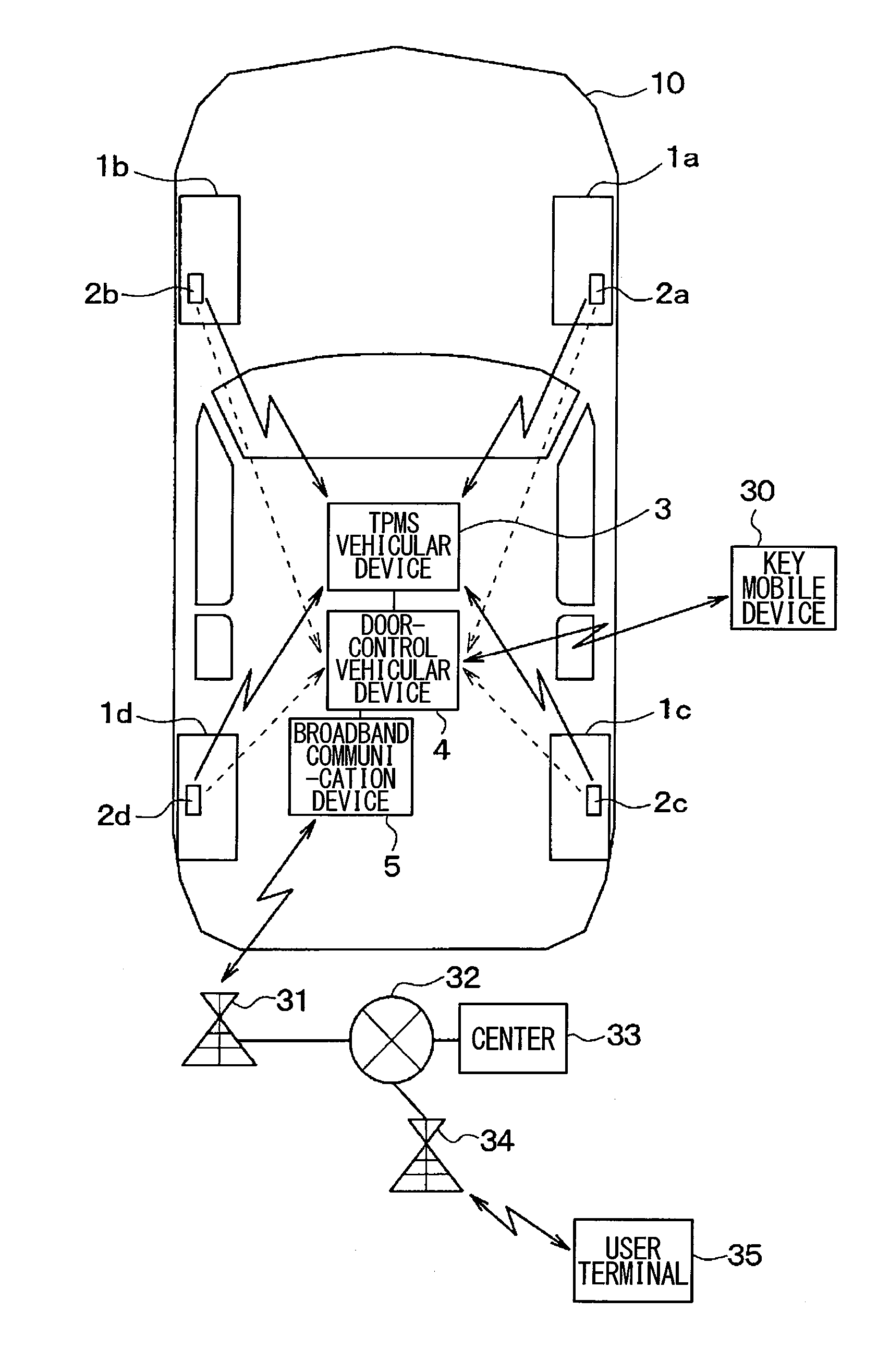
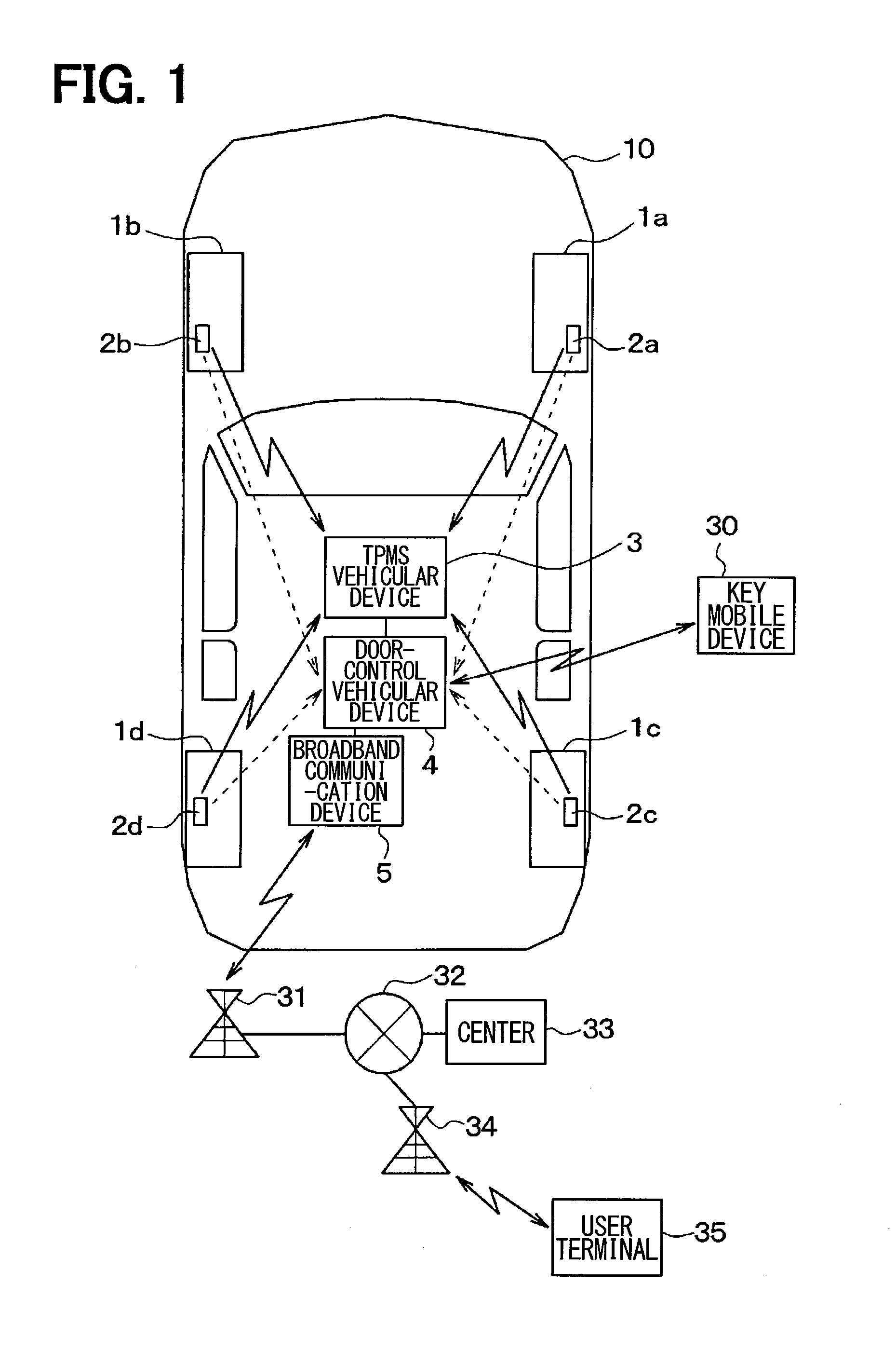
[0024]The following describes Embodiment 1 of the present disclosure. As illustrated in FIG. 1, a tire theft alarming system according to the present embodiment includes: sensor transmitters 2a through 2d, each of which is individually mounted on a plurality of tires 1a through 1d mounted to a vehicle 10 travelling with power of an engine as an internal combustion engine; a TPMS (tire pressure monitoring system) vehicular device 3 mounted on a vehicle body of the vehicle 10; a door-control vehicular device 4; a broadband communication device 5; and a key mobile device 10 carried by a user who uses the vehicle 10.

[0025]Each of the sensor transmitters 2a through 2d is always in operation regardless of IG of a vehicle being in an ON state or an OFF state (i.e., the main power supply of the vehicle being in an ON state or an OFF state). Subsequently, the air pressure of the tires 1a through 1d, on which the sensor transmitters 2a through 2d are individually mounted, and the acceleration...

embodiment 2

[0102]Embodiment 2 of the present disclosure is described in the following section. The present embodiment is different from Embodiment 1 in that the door-control vehicular device 4 carries out processing illustrated in FIG. 9 instead of processing illustrated in FIG. 4. It is noted that the steps appended by the identical numerical reference in FIGS. 4 and 9 carry out identical processing. Therefore, the descriptions of these steps are omitted or simplified herein.

[0103]The operation of the door-control vehicular device 4 in the present embodiment is different from Embodiment 1 in one respect. After a door-locking is outputted in Step 115, it is determined whether earthquake early warning in Step 117 is received. The earthquake early warning is early warning that notifies of an earthquake (or the main movement of an earthquake) to a user in advance, therefore, the earthquake early warning is set to be receivable by the broadband communication device 5. The broadband communication d...

embodiment 3

[0107]Embodiment 3 of the present disclosure is described in the following section. The present embodiment is an alternation of a part of Embodiments 1 and 2. The present embodiment is different from Embodiments 1 and 2 in that the TPMS vehicular device 3 has no wireless transmission function, and consequently the sensor transmitters 2a through 2d have no function for transmitting the notification of IG in an OFF state.

[0108]Thus, the sensor transmitters 2a through 2d do not receive a notification of IG in an OFF state, the incoming of timing of switching the transmission destination of a frame having air pressure and acceleration is detected based on the air pressure and acceleration of a tire detected by the sensor transmitters 2a through 2d.

[0109]The following section describes the differences between the present embodiment and Embodiments 1 and 2 in detail. The present embodiment configured by hardware is different from Embodiments 1 and 2 in that the TPMS vehicular device 3 do...


PUM


Abstract

A tire theft alarming system includes a vehicular device mounted to a vehicle and a mobile device carried by a user of the vehicle. When a main power supply of the vehicle is in an OFF state, the vehicular device transmits a radio wave including a first alarm based on having a variation in air pressure or acceleration of a tire, which is mounted to the vehicle, detected by a sensor transmitter for detecting and transmitting the air pressure of the tire or the acceleration applied to the tire. The mobile device carries out a warning notification to a user based on having reception of a radio wave including a first alarm transmitted by the vehicular device.

Description

CROSS REFERENCE TO RELATED APPLICATION[0001]This application is based on Japanese Patent Application No. 2012-272445 filed on Dec. 13, 2012, the disclosure of which is incorporated herein by reference.TECHNICAL FIELD[0002]The present disclosure relates to a tire theft alarm system.BACKGROUND ART[0003]The techniques for providing notification of theft of a tire mounted to a vehicle have been recently known. For example, Patent Document 1 discloses the technique in which a vehicle generates an alarm by sound and light when detecting a change in air pressure of a tire at the time of removing the tire from the vehicle.PRIOR ART LITERATURESPatent Literature[0004]Patent Literature 1: JP-2007-83911 ASUMMARY OF INVENTION[0005]However, the technique using light and sound as described above may not be effective for notifying of an abnormality to a user when the distance between a vehicle's parking position and the user's position (for example, residence) is longer.[0006]It is an object of the...

Claims


Application Information

Patent Timeline
IPC IPC(8): B60R25/102B60R25/34B60R25/10
CPCB60R25/102B60R25/34B60R25/1001B60C23/0437B60C23/0488B60C23/0418B60C23/0479
Inventor SHIGETOMI, ICHIRO
Owner DENSO CORP
Why Eureka
Try Eureka