
Method and apparatus for receiving signal in wireless communication system

Inactive Publication Date: 2011-03-03
SAMSUNG ELECTRONICS CO LTD
View PDF18 Cites 5 Cited by
  • Summary
  • Abstract
  • Description
  • Claims
  • Application Information

AI Technical Summary

Benefits of technology

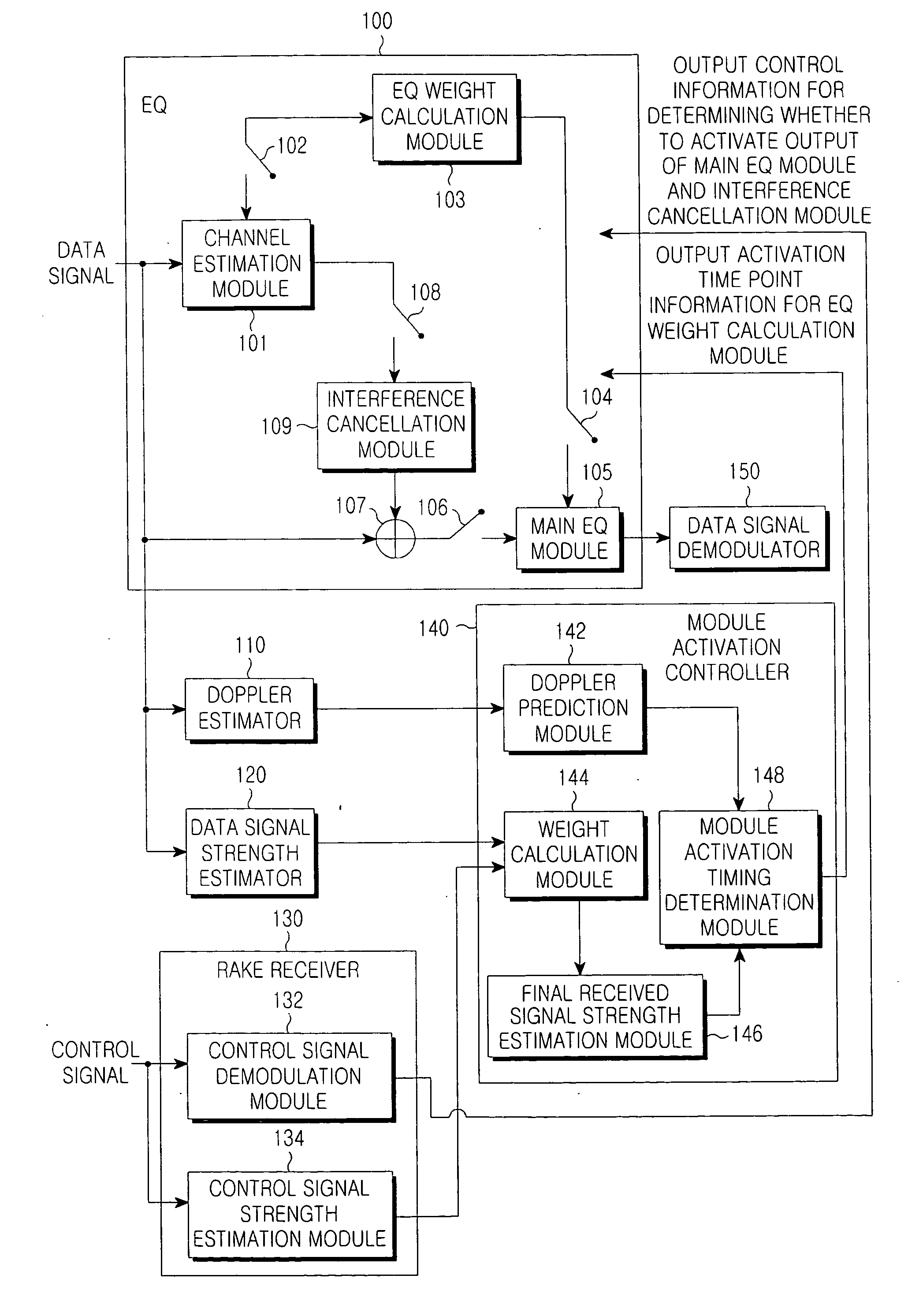
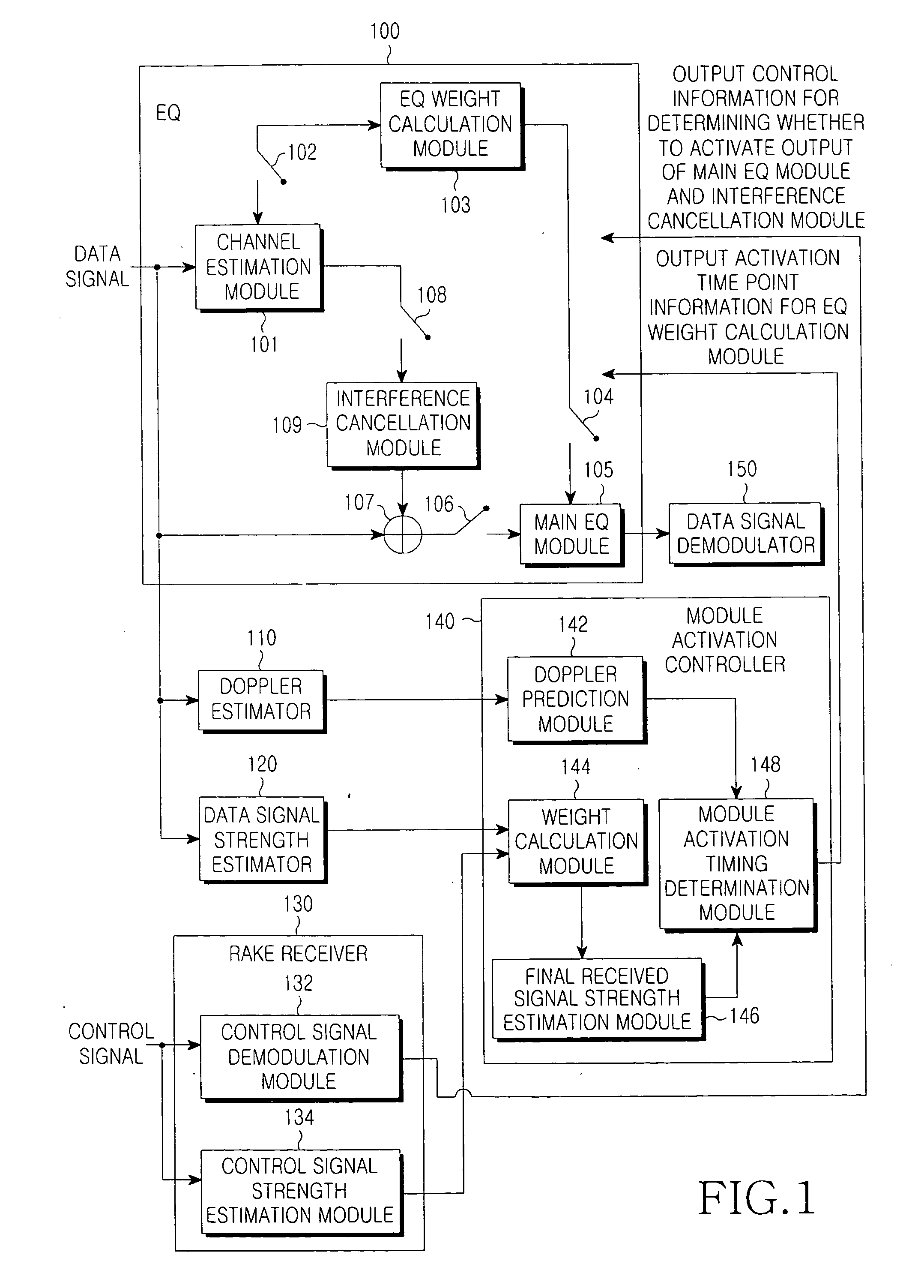
[0011]Further, the present invention provides a method and apparatus for receiving a signal in a wireless communication system, which prevents an EQ from being deteriorated in performance, and minimizes power consumption by reducing the active duration time of the EQ.
[0012]Further, the present invention provides a method and apparatus for receiving a signal in a wireless communication system, which can more efficiently operate an EQ depending on a modulation scheme used by a mobile terminal.

Problems solved by technology

The EQ may increase throughput in comparison to the RAKE receiver, but has a problem in that its power consumption is high.
However, when the RAKE receiver and EQ are alternately used according to SINR values, as mentioned above, it is impossible to always optimally operate the EQ and the RAKE receiver in a corresponding channel environment.
However, when the current SINR value corresponds to a boundary value that is set to distinguish between the operations of the RAKE receiver and the EQ, there is no telling which of the RAKE receiver and the EQ may be operated.
This may cause a problem in that, although the EQ can be more efficiently operated in a current channel environment, the RAKE receiver is actually operated.
By reason of this, it is impossible to always optimally operate the RAKE receiver and the EQ in a corresponding channel environment.
In this way, many problems are involved in alternately operating a RAKE receiver and an EQ to minimize power consumption of the EQ.

Method used


Image

  • Method and apparatus for receiving signal in wireless communication system
  • Method and apparatus for receiving signal in wireless communication system
  • Method and apparatus for receiving signal in wireless communication system

Examples


Embodiment Construction

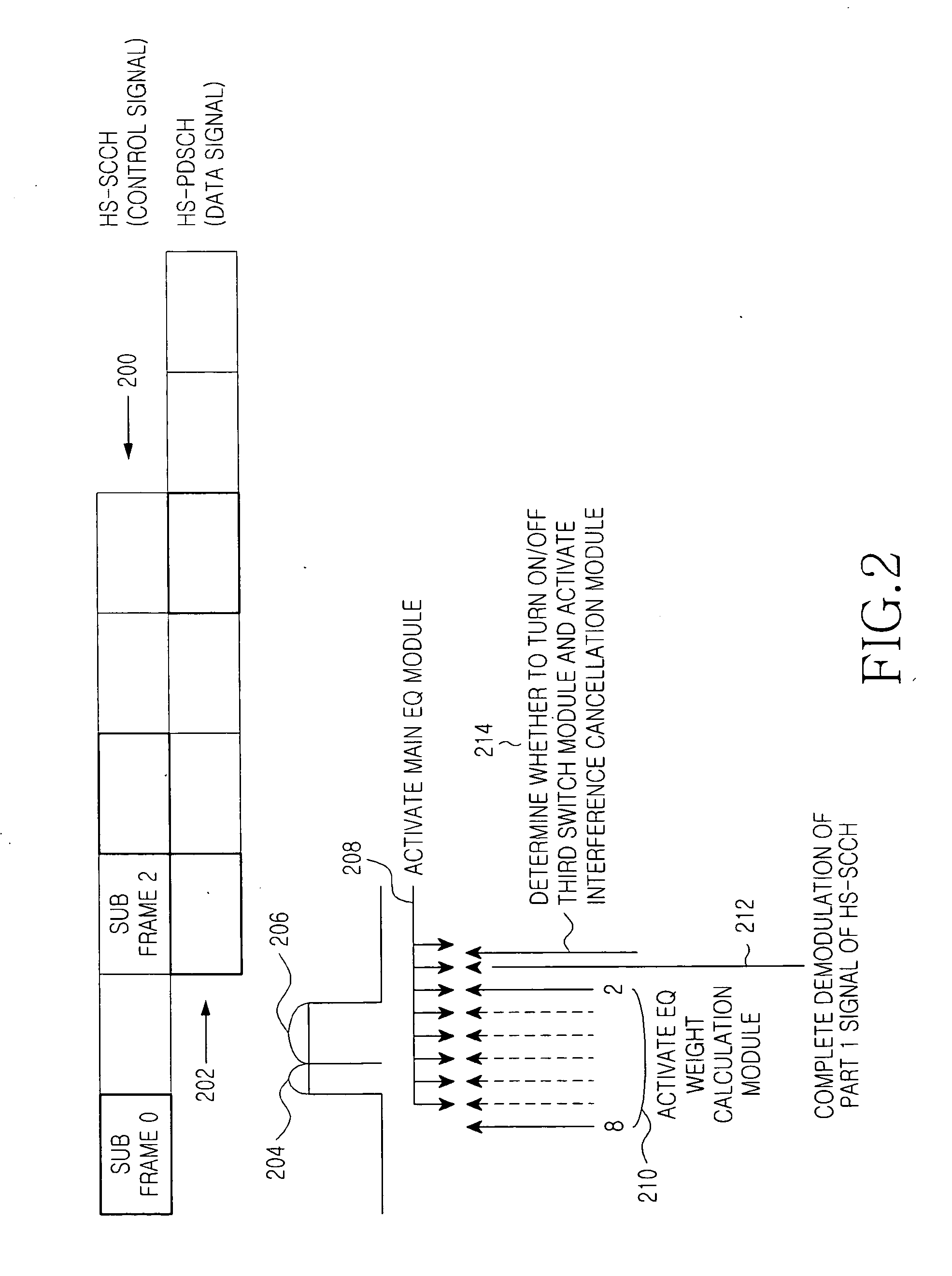
[0024]FIGS. 1 through 7, discussed below, and the various embodiments used to describe the principles of the present disclosure in this patent document are by way of illustration only and should not be construed in any way to limit the scope of the disclosure. Those skilled in the art will understand that the principles of the present disclosure may be implemented in any suitably arranged wireless communication system. Hereinafter, exemplary embodiments of the present invention will be described with reference to the accompanying drawings. It should be noted that the similar components are designated by similar reference numerals although they are illustrated in different drawings. Also, in the following description, a detailed description of known functions and configurations incorporated herein will be omitted when it may obscure the subject matter of the present invention. Further, it should be noted that only parts essential for understanding the operations according to the pres...


PUM


Abstract

A mobile terminal includes a channel estimation module that is maintained in an active state. A controller determines an activation time point of an equalizer weight calculation module for calculating a tap coefficient. The activation time point is earlier than an activation time point of a main equalizer module, and activates the equalizer weight calculation module at the activation time point so as to calculate the tap coefficient. When the equalizer weight calculation module's operation is completed, the controller activates the main equalizer module, detects a mobile terminal ID, activates an interference cancellation module, and controls the main equalizer module to provide a data signal demodulator with the data signal compensated for by the tap coefficient. A demodulator demodulates the compensated data signal.

Description

CROSS-REFERENCE TO RELATED APPLICATION(S) AND CLAIM OF PRIORITY[0001]The present application is related to and claims priority to an application entitled “Method and Apparatus for Receiving Signal in Wireless Communication System” filed in the Korean Industrial Property Office on Aug. 25, 2009, and assigned Serial No. 10-2009-0078771, the contents of which are hereby incorporated by reference.TECHNICAL FIELD OF THE INVENTION[0002]The present invention relates to a method and apparatus for receiving a signal in a wireless communication system.BACKGROUND OF THE INVENTION[0003]In order to increase throughput for received signals in a Code Division Multiple Access (CDMA)-based packet transmission system, such as High Speed Packet Access (HSPA), an equalizer (EQ) has been proposed as an alternative to a widely-used existing rake (RAKE) receiver.[0004]The EQ may increase throughput in comparison to the RAKE receiver, but has a problem in that its power consumption is high. Thus, the EQ is...

Claims


Application Information

Patent Timeline
IPC IPC(8): H04L27/01
CPCH04B1/1027H04B1/7103H04L1/0003H04L2025/03726H04L25/03019H04L2025/0342H04L2025/03681H04L1/20H04B1/06H04B1/69
Inventor WON, SEUNG-HWANYEO, SOO-BOKKIM, HO-ILKONG, SE-JIN
Owner SAMSUNG ELECTRONICS CO LTD
Learn More