Force-measuring device

a technology of force measurement and measuring device, which is applied in the direction of measurement device, apparatus for force/torque/work measurement, instruments, etc., can solve the problems of inability to achieve accurate and reliable, disadvantages in handling ability and measurement accuracy, and particularly strong expansion of expander elements, so as to improve the useful life of the spreader. , the effect of increasing the measuring accuracy

Active Publication Date: 2015-11-05
UNIFLEX HYDRAULIC
View PDF1 Cites 8 Cited by
  • Summary
  • Abstract
  • Description
  • Claims
  • Application Information

AI Technical Summary

Benefits of technology

[0021]According to a first embodiment, the expander element arrangement is formed by an expander sleeve, around which the thrust members are spaced apart from one another in circumferential direction and radially apart from the expander sleeve. The expander element arrangement consists of an expander element, which is formed by an expander sleeve. The expander sleeve is a central element, from the shell surface of which the thrust members are spaced apart as well as being spaced apart from one another in circumferential direction. This embodiment makes it possible to convert radial forces particularly uniformly to an axial force, thus permitting particularly accurate force measurement. Furthermore, a particularly firm joint between the expander sleeve and the spreader members joined thereto is possible. In addition, the transmission member can be disposed particularly well inside the expander sleeve and guided thereby. A radial gap is provided between the thrust members and the expander element, making it possible in a particularly simple way to expand the spreader elements in axial direction by the radial movement of the thrust members, albeit without squeezing the expander sleeve in radial direction. The material thickness of the expander sleeve is substantially limited only by the recesses for receiving the thrust members and the transmission member. Thereby it is possible to choose a particularly large material thickness, thus favoring the stability of the expander sleeve and making it possible to measure particularly high effective forces.
[0034]Finally, it is advantageously provided that the thrust chamfers and the sliding chamfers are formed by corresponding faces. The corresponding faces can be formed particularly simply by plane faces or round or conically turned faces. In a force-measuring device having eight thrust members, faces that as a whole are configured as an octagon are particularly advantageous. They contribute to making the thrust members slide at all times with an equally large part of their thrust faces on equally large parts of the sliding chamfers of the spreader members.

Problems solved by technology

None of the cited devices make it satisfactorily possible to achieve an accurate and reliable integrating measurement in the foregoing sense with simple means, especially in radial presses or collet chucks.
Furthermore, however, it is also possible to position both a workpiece and the force-measuring device simultaneously between the press jaws, although this may lead to disadvantages in terms of handling ability and measurement accuracy.
This contributes to the fact that radial forces acting on the thrust members may lead to particularly strongly pronounced expansion of the expander element.
The securing elements are able to protect the thrust members from moving inadvertently and undesirably far out of the recesses of the force-measuring device particularly reliably without jamming, and also do so redundantly because the thrust members are secured at both ends.

Method used


Image

  • Force-measuring device
  • Force-measuring device
  • Force-measuring device

Examples


Embodiment Construction

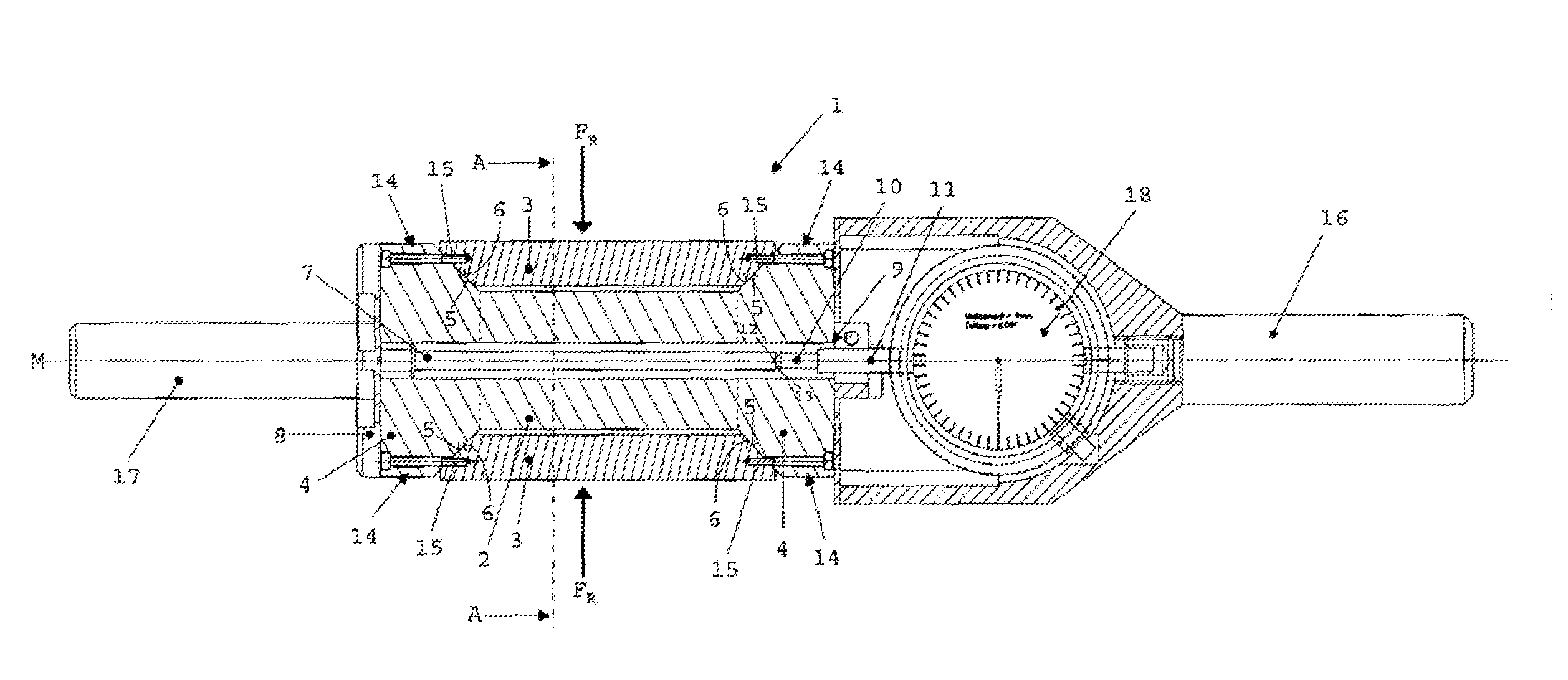
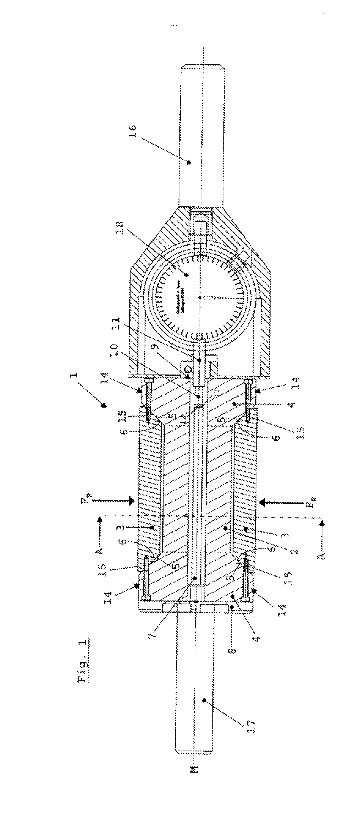
[0039]FIG. 1 shows an inventive force-measuring device 1 for measuring radial forces FR acting centrally perpendicular to an axis of measurement M. An expander element arrangement comprises a single expander element, which is formed by a central expander sleeve 2. Force-measuring instrument 1 further comprises eight thrust members 3 spaced apart from one another in circumferential direction. In FIG. 1, force-measuring device 1 is in unloaded condition, i.e. no external radial forces FR are acting on thrust members 3 (FR=0).

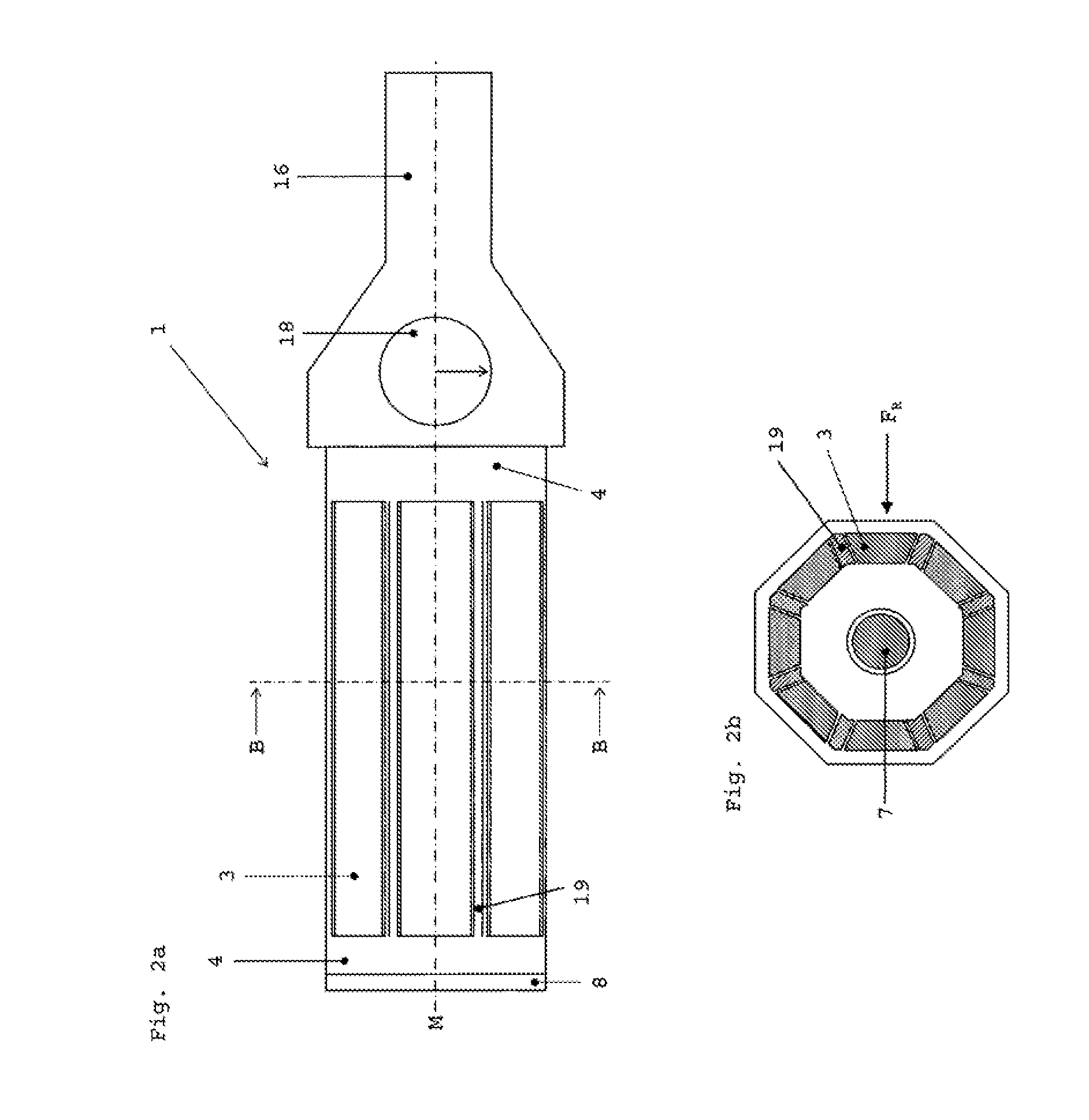
[0040]At each end, expander sleeve 2 is joined to respectively one spreader member 4, wherein expander sleeve 2 together with spreader members 4 forms a one-piece unit and spreader members 4 are constructed in the form of end plates. The unit comprising expander sleeve 2 and spreader members 4 consists of a material with a smaller modulus of elasticity than thrust members 3. Thrust members 3 are braced via thrust chamfers 5 on corresponding sliding chamfers 6 of s...


PUM

PropertyMeasurementUnit
forceaaaaaaaaaa
modulus of elasticityaaaaaaaaaa
radial forcesaaaaaaaaaa

Abstract

A force-measuring device is provided for integrating measurement of at least three radial forces acting centrally, in particular for radial presses or collets. The force-measuring device comprises a stretching-element assembly, which is concentric to a measurement axis and which comprises at least one stretching element. The force-measuring device also has at least three pressure elements spaced from each other in a circumferential direction, wherein two spreading elements are connected to the at least one stretching element at ends of the stretching element, the pressure elements are supported, by means of pressure inclines, on corresponding sliding inclines of the spreading elements, a transmitting element is fastened to a first of the two spreading elements, and a measuring sensor acts between the second of the two spreading elements and the transmitting element.

Description

CROSS REFERENCE TO RELATED APPLICATIONS[0001]This application is a continuation under 35 U.S.C. §120 of International Application PCT / EP2014 / 001179, filed May 2, 2014, which claims priority to German Application 10 2013 007 535.1, filed May 3, 2013, the contents of each of which are incorporated by reference herein.FIELD OF THE INVENTION[0002]The invention relates to a force-measuring device for integrating measurement of at least three centrally acting radial forces, especially for radial presses or collet chucks, comprising an expander element arrangement concentric with an axis of measurement and comprising at least one expander element.BACKGROUND[0003]In many technical applications, especially in connection with radial presses and collet chucks, three of more radial forces may be acting centrally, i.e. toward a central axis of measurement. In the case of a radial press, for example, the number of radial forces occurring may be determined by the number of press jaws present. A ne...

Claims


Application Information

Patent Timeline
Patent Type & Authority Applications(United States)
IPC IPC(8): G01L5/12
CPCG01L5/12G01L1/04G01L5/0085
Inventor VON WAITZ, HARALDBAUMGARTNER, CARSTENHEJPLIK, VACLAV
Owner UNIFLEX HYDRAULIC
Why Eureka
Try Eureka