Scissors lifting table and method of assembling a scissors lifting table

Inactive Publication Date: 2015-11-12
MOHR CHRISTOPH
View PDF8 Cites 13 Cited by
  • Summary
  • Abstract
  • Description
  • Claims
  • Application Information

AI Technical Summary

Benefits of technology

[0016]During the assembly of the scissors the use of the same parts can also be advantageously optimized if identical scissor blades are used as the inner and outer scissor blades for the construction of the particular right and left scissors packet. This makes it possible to keep prefabricated inner and outer scissor blades available in fixed sizes and designs. The inner and outer scissor blades selected from the stored scissor blades are then connected to each other by a central support, wherein the relative position of the inner scissor blade and the outer scissor blade to one another results by the disposition of the scissor blades during the connection to the central support, and therefore the use of the scissors packet produced is set as a left or a right scissors packet of the scissors of the lifting table. The t

Problems solved by technology

It was previously assumed that due to the great number of different customer specifications the storing of parts prefabricated in fixed sizes was not worthwhile for such lifting tables since too great a number of differently sized com

Method used


Image

  • Scissors lifting table and method of assembling a scissors lifting table
  • Scissors lifting table and method of assembling a scissors lifting table
  • Scissors lifting table and method of assembling a scissors lifting table

Examples


Embodiment Construction

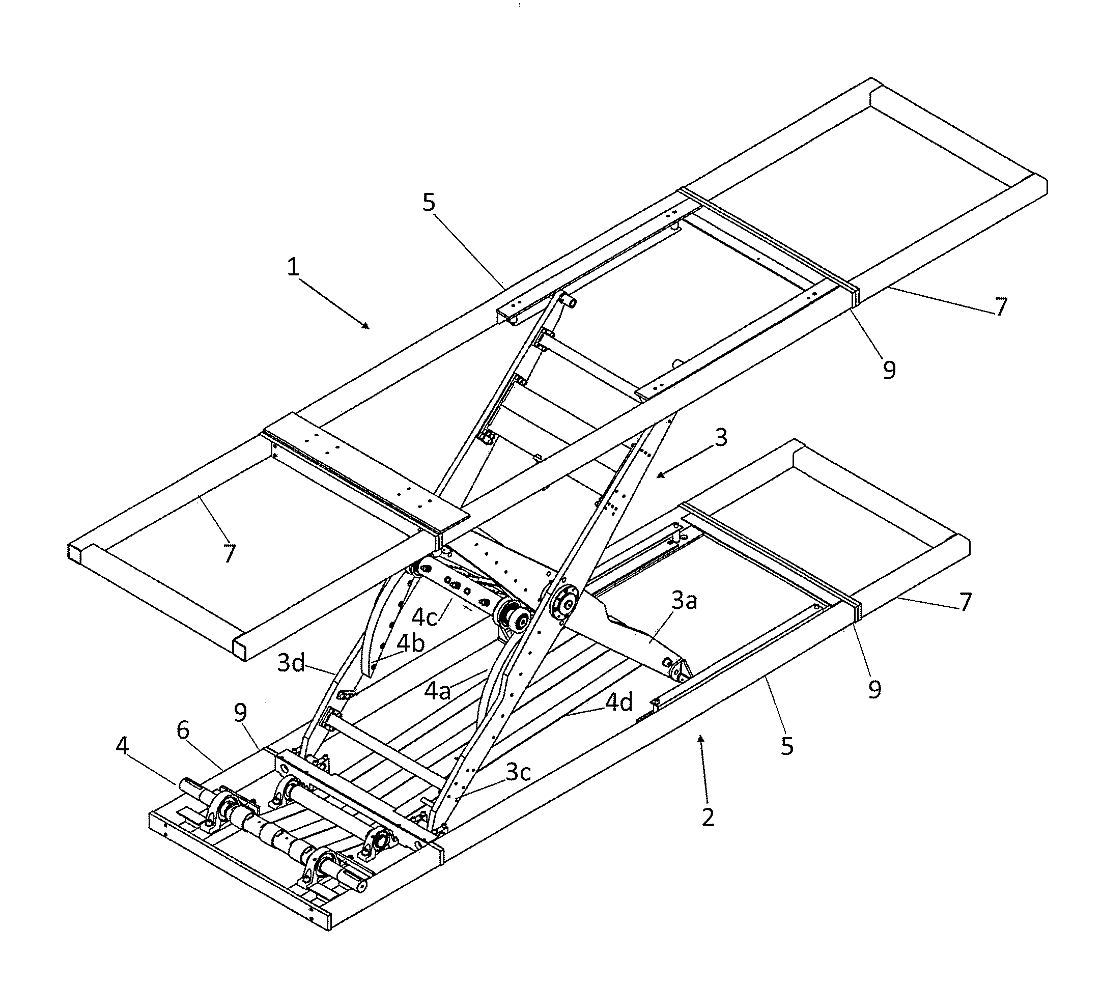
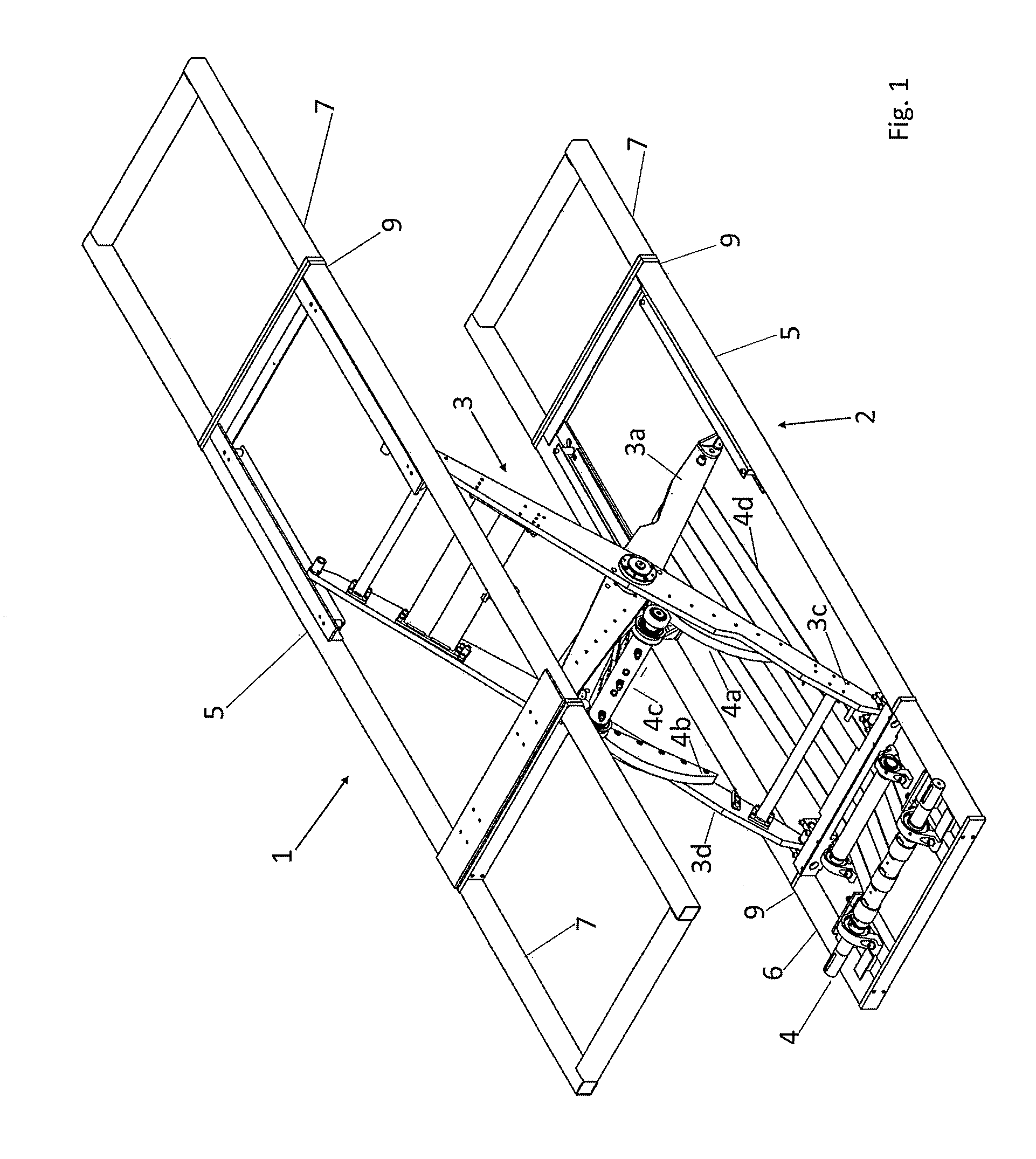
[0021]The exemplary scissors lifting table in accordance with the invention comprises an upper frame module 1, FIG. 1, and a lower frame module 2 connected by the scissors assembly 3. A central frame module 5 is a component of both the upper frame module 1 and of the lower frame module 2. Other components of the upper frame module 1 and of the lower frame module 2 are extension modules 7 fastened to one or more sides of the central frame module 5 in order to allow the upper and / or lower frame modules 1, 2 to be provided at a customer specific length. To this end, the extension modules 7 are fastened to the central frame modules 5 utilizing fastening elements 9, in the example shown in the form of flanges and screws (not shown for the sake of clarity).

[0022]The drive unit 4 is received or located on a drive module 6 that is connected like the extension modules 7 by a fastening element 9 to a central frame module 5 on one side side.

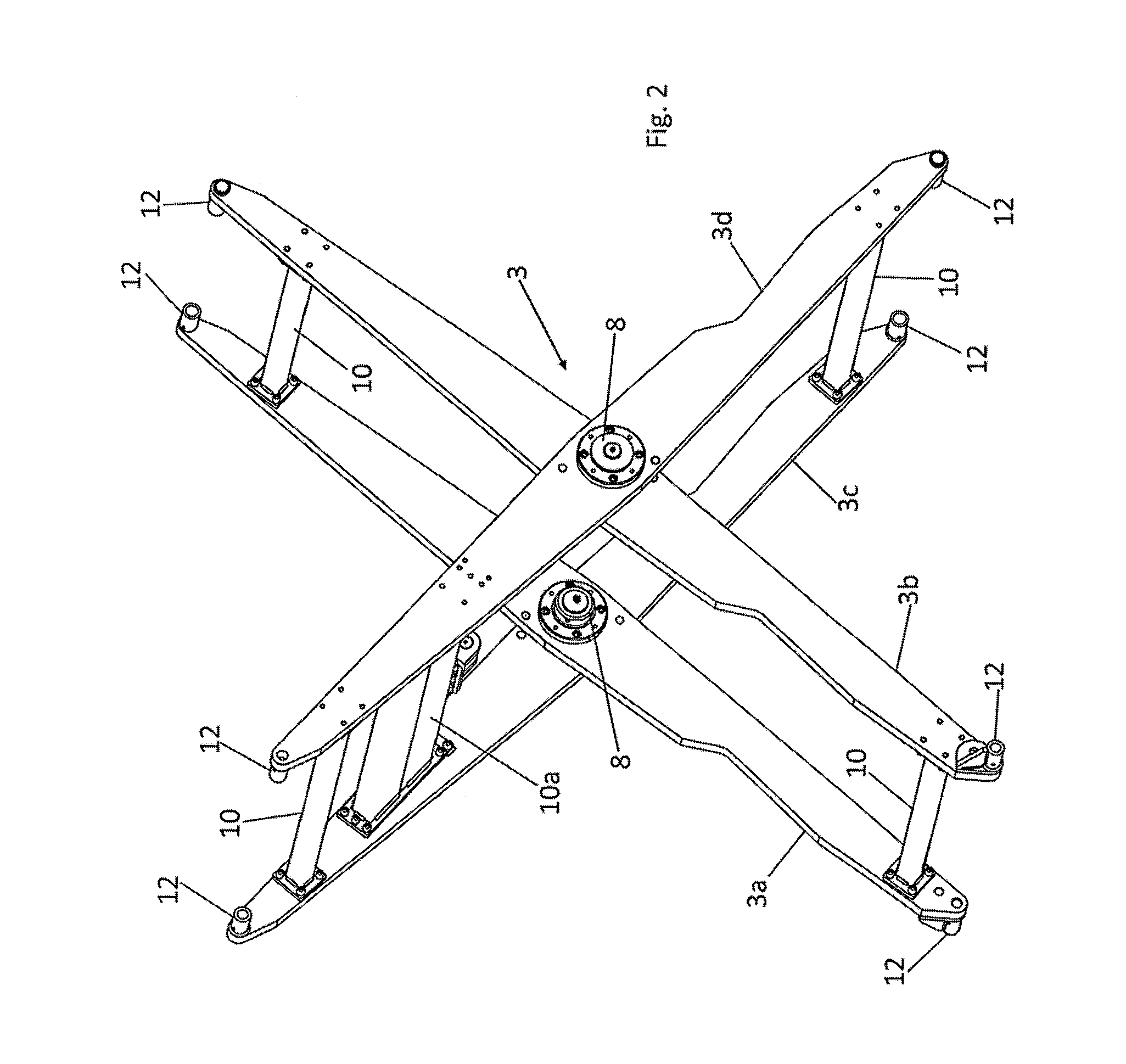
[0023]In the exemplary embodiment shown, the scissors...


PUM


Abstract

A scissors lift comprises an upper frame module (1) and a lower frame module (2), a scissor mechanism (3) and a drive unit (4). The upper frame module (1) and the lower frame module (2) are connected by the scissor mechanism (3) in such a way that a lifting movement, by which the spacing between the upper frame module (1) and lower frame module (2) changes, is rendered possible. The scissors lift, particularly the upper frame module (1) and/or the lower frame module (2), have a central portion (5) to which extension 6 and/or 7 that are pre-produced in fixed sizes and are fitted together in the manner of a modular construction system to make a scissors lifting lift of desired size.

Description

TECHNICAL FIELD[0001]The invention relates to a scissors lifting table and to a method of assembling a scissors lifting table.BACKGROUND INFORMATION[0002]Scissors lifting tables of the type under discussion have an upper and a lower frame module that are connected by scissors in such a manner that a lifting movement is made possible by which the distance between the upper and the lower frame module changes. In order to make possible the carrying out of the movement, the scissors lifting tables furthermore comprise a drive unit.[0003]As a rule the scissors consist of two pairs of crossed scissor blades that are connected to one another in pairs by a middle support and are connected to one another at a distance by struts running in the direction of the width of the scissors lifting table. The struts running in the direction of width connect the inner and the other scissor blades to each other.[0004]The inner or outer scissor blades are articulated to one of the frame modules in the ar...

Claims


Application Information

Patent Timeline
IPC IPC(8): B66F7/06B66F7/28
CPCB66F7/28B66F7/065B66F2700/09B66F7/06
Inventor MOHR, CHRISTOPH
Owner MOHR CHRISTOPH
Why Eureka
Try Eureka