Radio-Frequency System

a radio frequency and system technology, applied in the field of radio frequency systems, can solve the problems of reducing system performance, limited available space, and difficult to accommodate another set of array antennas, and achieve the effect of increasing the sensing range of array antennas and enlarging the disposal area

Active Publication Date: 2015-11-12
WISTRON NEWEB
View PDF8 Cites 5 Cited by
  • Summary
  • Abstract
  • Description
  • Claims
  • Application Information

AI Technical Summary

Benefits of technology

[0007]It is therefore a primary objective of the present invention to provide an RF system to increase sensing range of the array antenna without substantially enlarging the disposal area.

Problems solved by technology

Due to hardware limitation, false alarm is usually caused and system performance is degraded.
Since shock-absorbing Styrofoam or glass fibers are usually disposed inside the vehicle bumpers, the available space is limited.
It is hard to accommodate another set of array antennas.

Method used


Image

  • Radio-Frequency System
  • Radio-Frequency System
  • Radio-Frequency System

Examples


Embodiment Construction

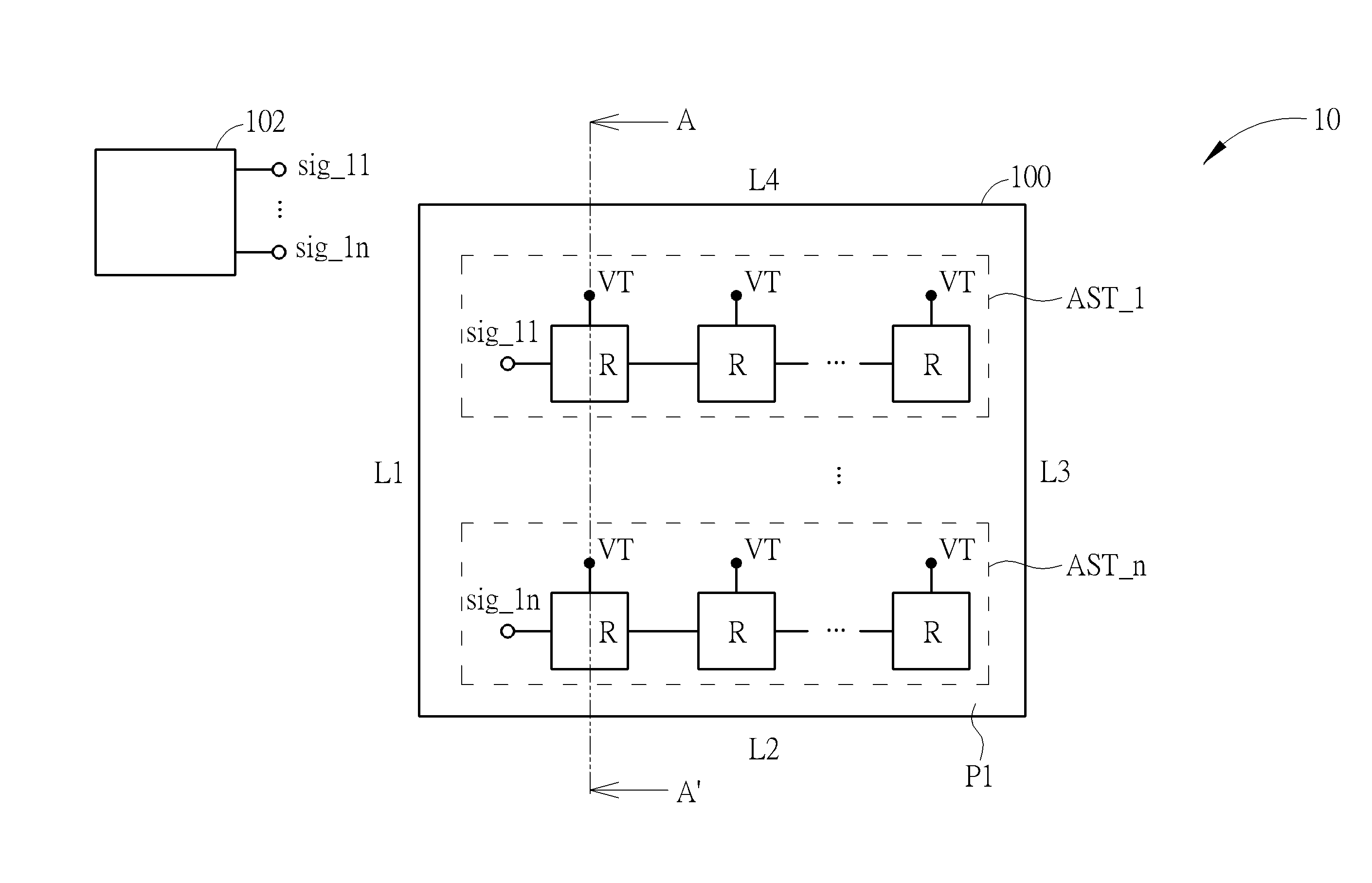
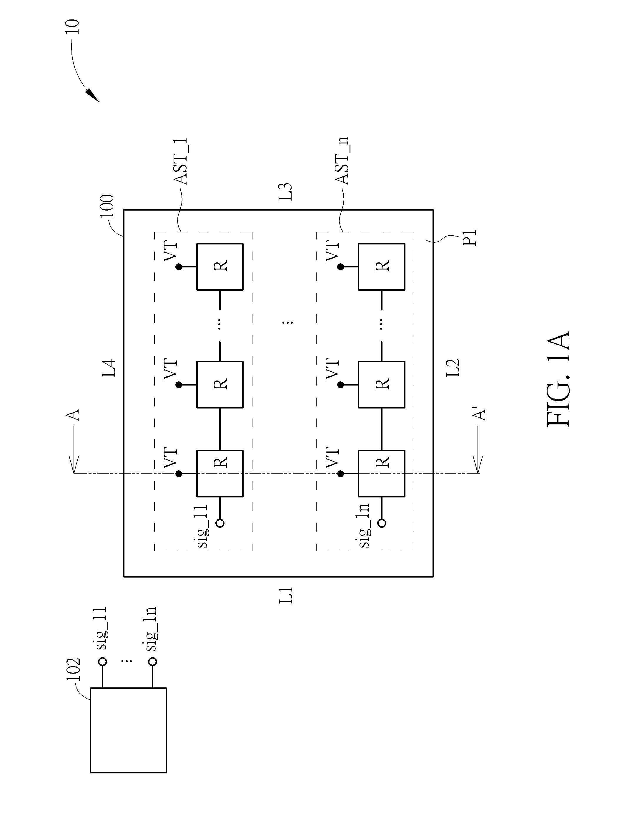
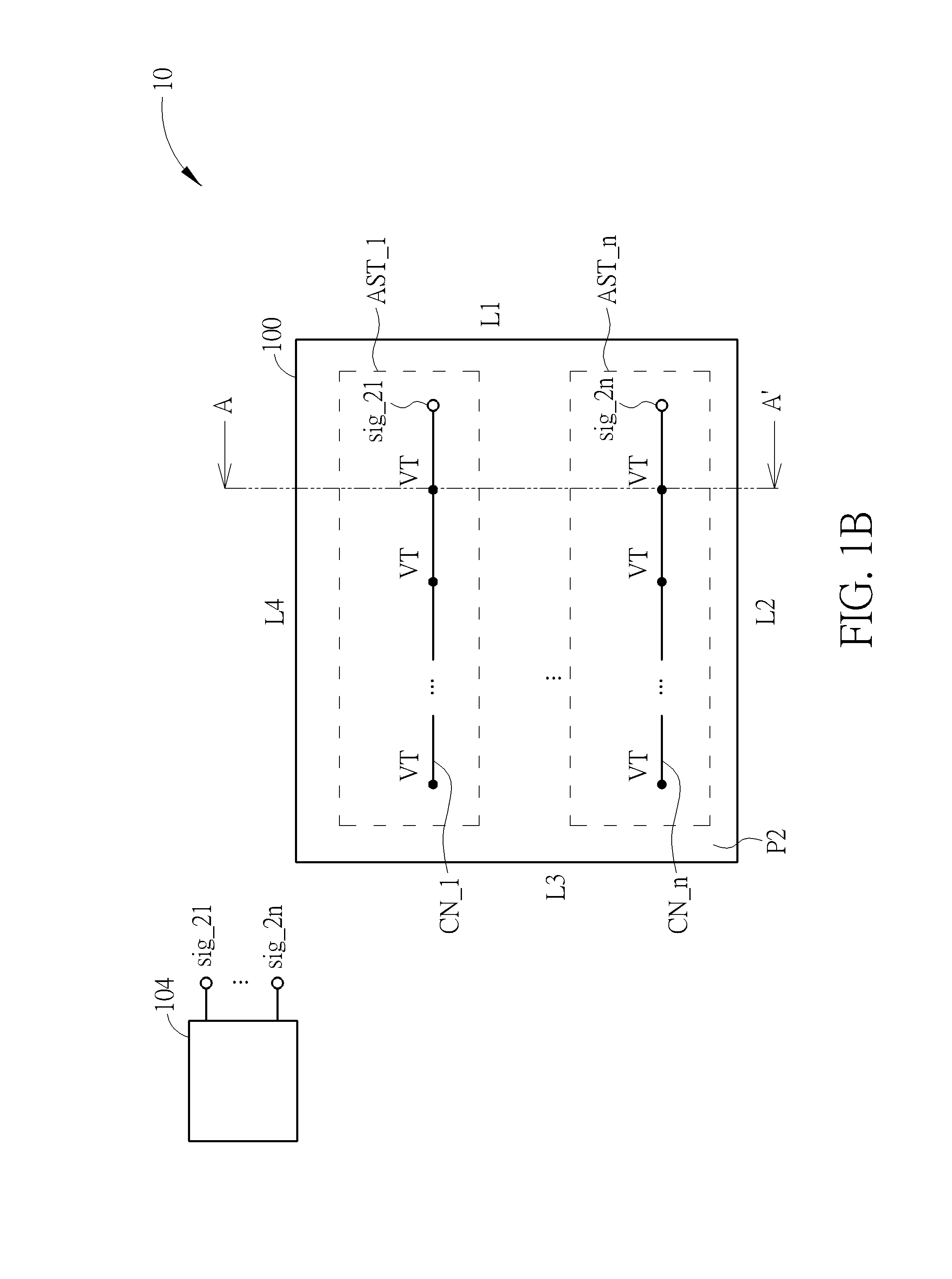
[0015]Please refer to FIGS. 1A to 1C. FIGS. 1A and 1B are schematic diagrams of a first plane P1 and a second plane P2 of a radio-frequency (RF) system 10 according to an embodiment of the present invention. FIG. 1C is a sectional side view along with a line A-A′ in FIG. 1A. The RF system 10 may be a microwave transceiving network of a radar system such as a vehicle array antenna, and not limited herein. The RF system 10 comprises a substrate 100, antenna strings AST_1-AST_n, wires CN_1-CN_n, connecting units VT, a first RF processing module 102 and a second RF processing module 104. For clarity, four sides L1-L4 are annotated for the substrate 100 in FIGS. 1A and 1B to distinguish the illustrated directions of the first plane P1 and the second plane P2. As shown in FIG. 1C, the first plane P1 and the second plane P2 are a top plane (or surface) and a bottom plane (or surface) of the substrate 100, respectively. Furthermore, the substrate 100 may be classified into an antenna substr...


PUM


Abstract

A radio-frequency (RF) system includes a substrate; a plurality of antenna strings, formed on a first plane of the substrate, each comprising a plurality of radiating units connected in a sequence, wherein the plurality of antenna strings are classified into a first group and a second group; a plurality of wires, formed on a second plane of the substrate, for transmitting RF signals; a plurality of connecting units, disposed in the substrate, for coupling the plurality of wires and antenna strings of the second group; a first RF processing module, for transmitting or receiving RF signals via antenna strings of the first group, and a second RF processing module, for coupling to the antenna strings of the second group through the plurality of wires and the plurality of connecting units, so as to transmit or receive RF signals via the antenna strings of the second group.

Description

BACKGROUND OF THE INVENTION[0001]1. Field of the Invention[0002]The present invention relates to a radio-frequency (RF) system, and more particularly, to an RF system capable of providing additional transmitting and receiving capabilities without substantially enlarging disposal area.[0003]2. Description of the Prior Art[0004]An array antenna is an antenna system composed of a plurality of identical antennas arranged in accordance with a specific rule. Through proper arrangement of antenna element of the array antenna, a specific radiation pattern is achieved to concentrate a main beam at a specific direction to transmit signals. For example, for vehicle radar systems, the array antenna is configured to perform 2-dimensional sensing on horizontal direction. However, in practical applications, the 2-dimensional sensing over only horizontal direction may receive reflections from objects (such as notice boards, traffic lights, bridges, buildings, etc.) which are higher than a horizonta...

Claims


Application Information

Patent Timeline
Patent Type & Authority Applications(United States)
IPC IPC(8): G01S7/42G01S13/931
CPCG01S7/42G01S7/006G01S7/03H01Q21/0006H01Q23/00G01S13/931
Inventor HUANG, GUO-SHUHSIAO, HSIN-LUNG
Owner WISTRON NEWEB
Why Eureka
Try Eureka