Antenna module and electronic apparatus

an antenna module and electronic equipment technology, applied in the direction of antennas, antenna details, electrical equipment, etc., can solve the problems of large human health damage, small sensing range of sensors, and antennas that cannot perform detection, so as to achieve better radiation performance and large sensing range

Active Publication Date: 2013-08-29
COMPAL ELECTRONICS INC
View PDF5 Cites 3 Cited by
  • Summary
  • Abstract
  • Description
  • Claims
  • Application Information

AI Technical Summary

Benefits of technology

[0009]The invention is directed to an antenna module, which has a relatively large sensing range and a better radiation performance.
[0010]The invention provides an electronic apparatus having the aforementioned antenna module to achieve better radiation performance, which avails maintaining communication quality.
[0013]According to the above description, the top surface and the bottom surface of the circuit board respectively of the invention have the communication antenna pattern and the proximity sensor, and the proximity sensor is electrically connected to the sensing antenna patch, and the orthogonal projection of the communication antenna pattern overlaps the sensing antenna patch. In this way, a sensing range of the proximity sensor is enlarged to satisfy a safety requirement, and meanwhile the electronic apparatus using the antenna module may maintain the requirements in safety and communication quality.

Problems solved by technology

Generally speaking, electromagnetic waves radiated by an antenna may often be harmful to human health, so that the Federal Communications Commission (FCC) specifies a specific absorption ratio (SAR) for electronic apparatus, so as to limit radiation energy of the electronic apparatus or a maximum radiation limit of the electronic apparatus.
However, the sensors can only perform object detection at the two ends of the communication antenna, so that a sensing range of the sensors is relatively small, and even a central part of the antenna cannot perform the detection.
Therefore, how to satisfy the safety requirement specified by the SAR value and consider communication quality of the electronic apparatus simultaneously has become a major problem.

Method used


Image

  • Antenna module and electronic apparatus
  • Antenna module and electronic apparatus
  • Antenna module and electronic apparatus

Examples


Embodiment Construction

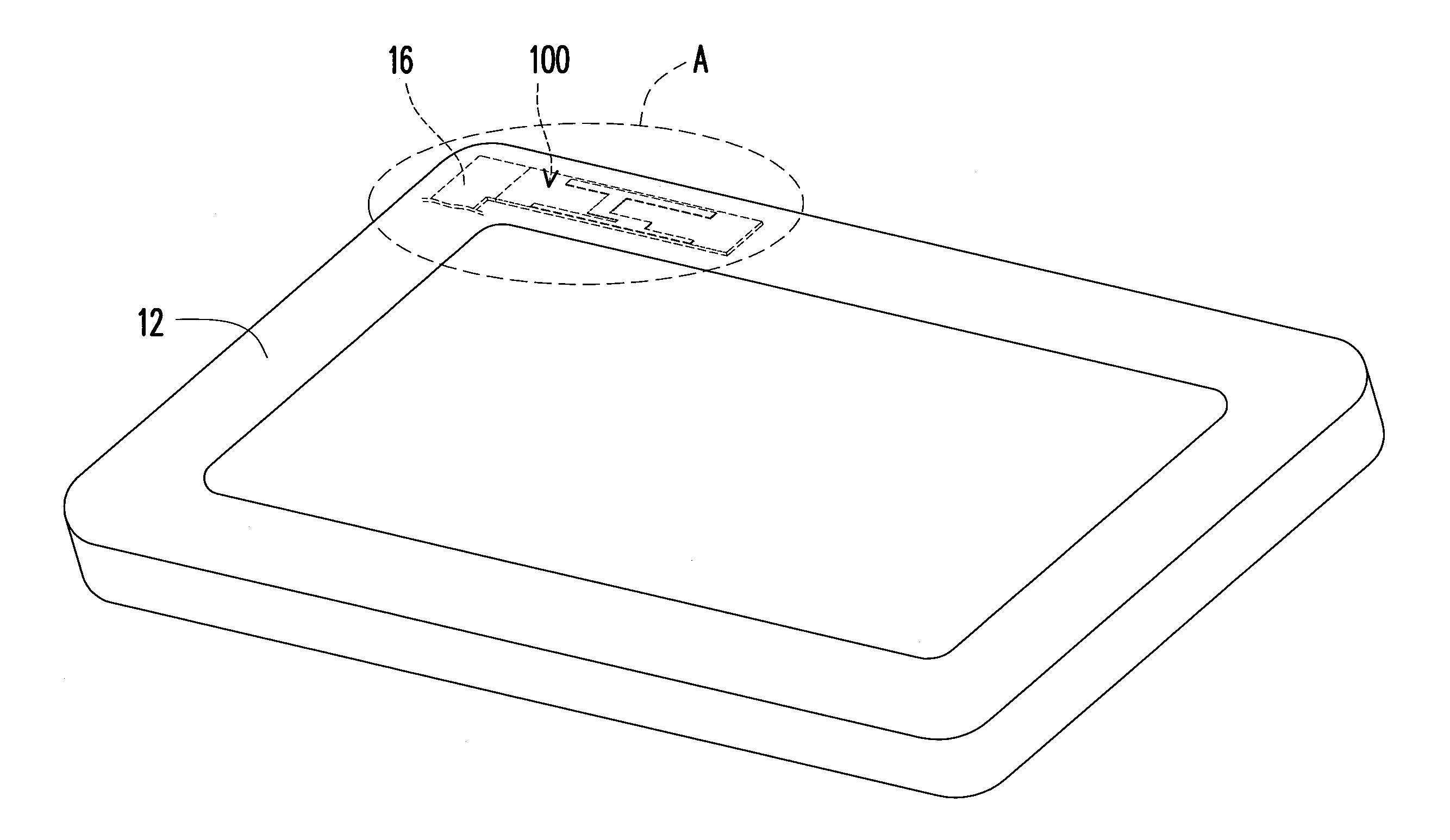
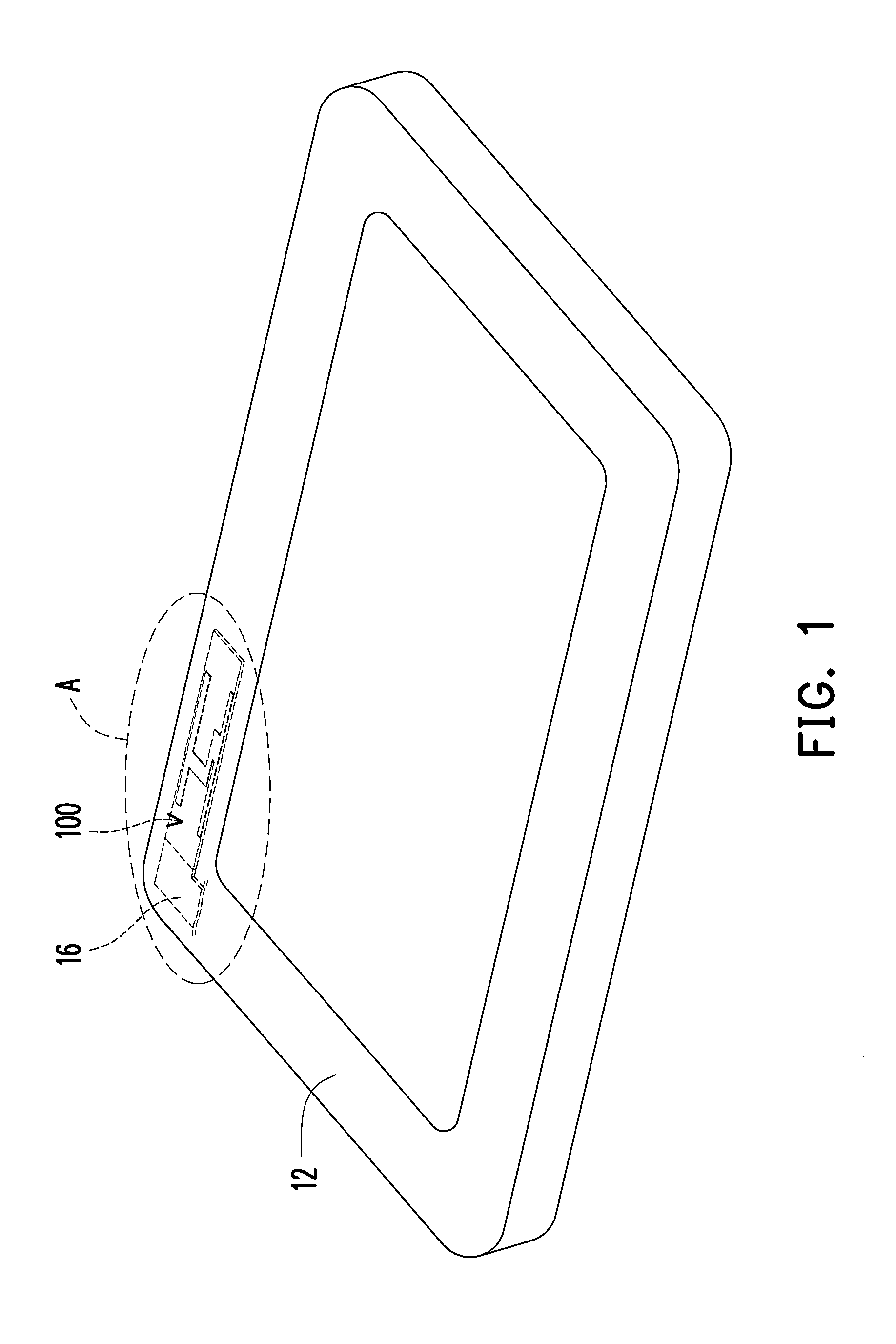
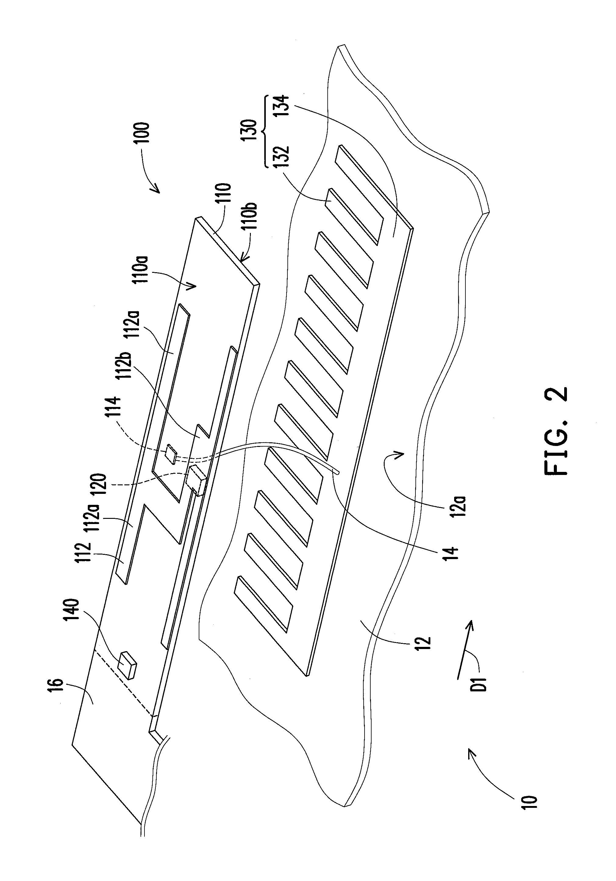
[0021]FIG. 1 is a perspective view of an electronic apparatus according to an embodiment of the invention. FIG. 2 is an exploded view of an antenna module of FIG. 1 at a part A. FIG. 3 illustrates orthogonal projections of a communication antenna pattern and a sensing antenna patch of FIG. 2 on an inner surface of a housing. Referring to FIG. 1, FIG. 2 and FIG. 3, in the present embodiment, the electronic apparatus 10 includes a housing 12 and an antenna module 100, wherein the electronic apparatus 10 is, for example, a handheld electronic device such as a tablet computer or a smart phone, etc.

[0022]The antenna module 100 includes a circuit board 110, a proximity sensor 120 and a sensing antenna patch 130. The circuit board 110 is disposed in the housing 12, and has a top surface 110a and a bottom surface 110b opposite to the top surface 110a. The circuit board 110 has a communication antenna pattern 112 on the top surface 110a for receiving and transmitting wireless signals. The co...


PUM


Abstract

An antenna module and an electronic apparatus are provided. The electronic apparatus includes a housing and the antenna module. The housing has an inner surface. The antenna module includes a circuit board, a proximity sensor and a sensing antenna patch. The circuit board is disposed in the housing, and has a top surface and a bottom surface opposite to the top surface. The circuit board has a communication antenna pattern on the top surface. The proximity sensor is mounted on the bottom surface. The sensing antenna patch is assembled on the inner surface of the housing and electrically connected to the proximity sensor. An orthogonal projection of the communication antenna pattern on the inner surface overlaps the sensing antenna patch on the inner surface.

Description

CROSS-REFERENCE TO RELATED APPLICATION[0001]This application claims the priority benefit of Taiwan application serial no. 101106322, filed on Feb. 24, 2012. The entirety of the above-mentioned patent application is hereby incorporated by reference herein and made a part of this specification.BACKGROUND OF THE INVENTION[0002]1. Field of the Invention[0003]The invention relates to an electronic module and an electronic apparatus. Particularly, the invention relates to an antenna module and an electronic apparatus using the same.[0004]2. Description of Related Art[0005]Generally speaking, electromagnetic waves radiated by an antenna may often be harmful to human health, so that the Federal Communications Commission (FCC) specifies a specific absorption ratio (SAR) for electronic apparatus, so as to limit radiation energy of the electronic apparatus or a maximum radiation limit of the electronic apparatus.[0006]Besides, in order to ensure communication quality of the electronic apparatu...

Claims


Application Information

Patent Timeline
Patent Type & Authority Applications(United States)
IPC IPC(8): H01Q1/24
CPCH01Q1/245H01Q1/38
Inventor HUNG, CHEN-TAHUANG, WEI-CHIHWENG, CHAO-CHUHWANG, CHIEH-TSAO
Owner COMPAL ELECTRONICS INC
Why Eureka
Try Eureka