Powder supply method in cladding

a technology of cladding and powder, which is applied in the direction of machines/engines, manufacturing tools, mechanical equipment, etc., can solve the problems of difficult to stabilize the difficulty of uniform supply of powder to be supplied to the respective filling regions of etc., to reduce the variability of the powder supply amount to be supplied to the powder cladding nozzle, the effect of stabilizing the quality of the clad layer and restrain th

Active Publication Date: 2015-11-19
TOYOTA JIDOSHA KK
View PDF1 Cites 16 Cited by
  • Summary
  • Abstract
  • Description
  • Claims
  • Application Information

AI Technical Summary

Benefits of technology

[0024]As can be understood from the above description, the powder supply method in cladding according to the present invention is performed such that, in the cladding in which a machining part of a workpiece is irradiated with a laser beam and powder is discharged to a laser applied part of the machining part so as to form a clad layer in the machining part, the outlet pressure of the powder-cladding-nozzle side of the supply pipe configured to supply the powder from the p

Problems solved by technology

However, as described in the conventional technique described in JP 2005-219060 A, even if the supply paths through which the powder is supplied to the respective filling regions of the powder cladding nozzle are set to have the same feeding distance and the powder is simultaneously discharged to the machining part from the respective filling re

Method used


Image

  • Powder supply method in cladding
  • Powder supply method in cladding
  • Powder supply method in cladding

Examples


Embodiment Construction

[0034]With reference to drawings, the following describes an embodiment of a powder supply method in cladding according to the present invention.

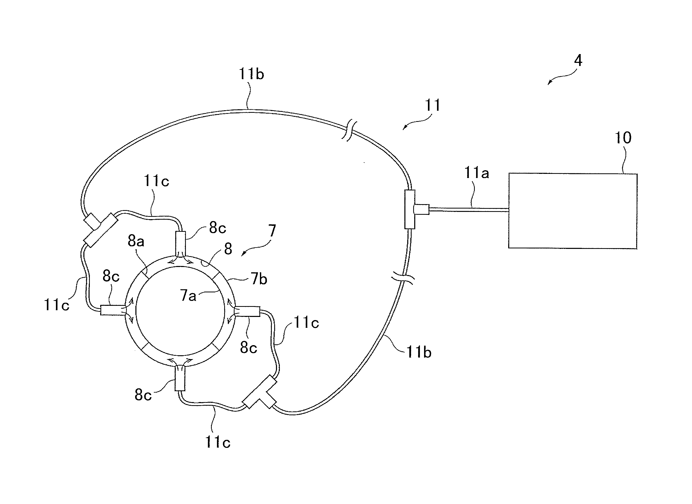
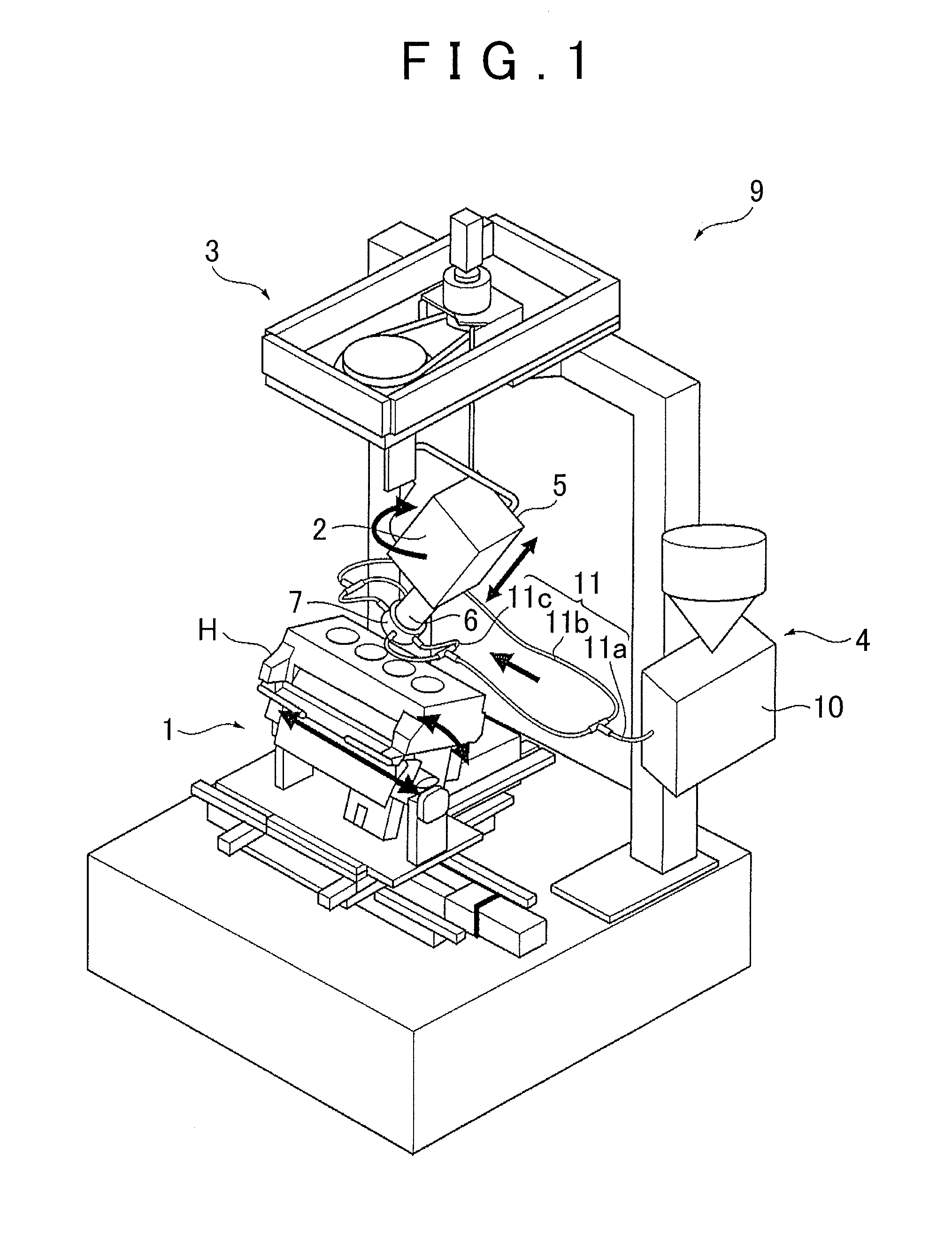
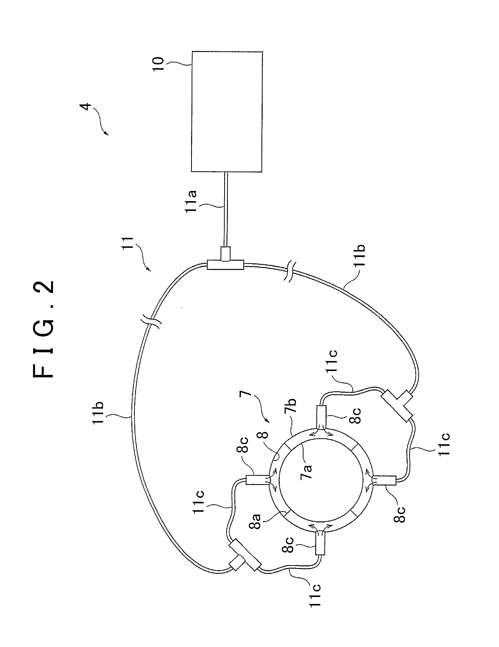
[0035]First, with reference to FIGS. 1 and 2, the following generally gives an outline of an example of a laser cladding device to which the powder supply method in cladding of the present invention is applied, and a powder supply device thereof. FIG. 1 is a perspective view diagrammatically illustrating a main configuration of the laser cladding device to which the powder supply method in cladding of the present invention is applied, and FIG. 2 is a schematic view diagrammatically illustrating a main configuration of the powder supply device illustrated in FIG. 1;

[0036]A laser cladding device 9 illustrated in FIG. 1 is a device configured to perform laser clad machining (cladding) on a valve seat portion of a cylinder head H, for example. The laser cladding device 9 includes: a cylinder head holding device 1 configured to hold the cylinder...


PUM

PropertyMeasurementUnit
Pressureaaaaaaaaaa
Pressureaaaaaaaaaa
Lengthaaaaaaaaaa

Abstract

In a powder supply method in cladding, an outlet pressure of a coaxial-nozzle side of a supply pipe connecting a feeder to a coaxial nozzle is set within a predetermined range, and powder is supplied from the feeder to the coaxial nozzle.

Description

INCORPORATION BY REFERENCE[0001]The disclosure of Japanese Patent Application No. 2014-100596 filed on May 14, 2014 including the specification, drawings and abstract is incorporated herein by reference in its entirety.BACKGROUND OF THE INVENTION[0002]1. Field of the Invention[0003]The present invention relates to a powder supply method in cladding, e.g., a powder supply method in cladding in which a machining part of a workpiece is irradiated with a laser beam and powder such as powder metal is discharged to a laser applied part of the machining part so as to form a clad layer in the machining part.[0004]2. Description of Related Art[0005]For example, in order to improve durability of a valve seat of a cylinder head for an engine and to increase its design flexibility, such laser machining has been known that a laser beam is applied to the valve seat while a powder-shaped (powdery) cladding material is supplied thereto, and the valve seat is rotated relative to the laser beam so as...

Claims


Application Information

Patent Timeline
IPC IPC(8): B23K26/14
CPCB23K26/1411B23K26/1464B23K26/1447B23K26/14B23K26/144B23K26/147B23K26/342C23C24/106F01L3/04B23K26/1462
Inventor IWATANI, SHINGOSATO, AKIOISHIKAWA, YOSHINORIKIDERA, KENJI
Owner TOYOTA JIDOSHA KK
Why Eureka
Try Eureka